[ Bus & Message Reference ]
Reverse-engineering reference for FCA / Stellantis CAN bus: bus topology (CAN-C vs CAN-IHS), TIPM/TIPMCGW gateway behavior, and decoded message IDs lifted from the scripts on the parent page with byte-level evidence — $1C0 RKE payloads, $122 ignition state, $350 RTC layout, UDS service path used by 3rd_brakelight.sh ($2D3 / $620 / DID $D1B3), and the full JEEP live-data message map extracted from pyJeepCan.py. Includes candidate IDs for fields commonly broadcast but not yet decoded here, plus the usual model/year caveats.
NOTE — platform specificity:  Most of the message IDs,
byte layouts, and decoded payloads documented here were captured on
JEEP-platform vehicles (Wrangler / Gladiator / Grand Cherokee / similar).
FCA / Stellantis reuses some IDs across its lineup (Chrysler, Dodge,
Ram, Alfa Romeo) but reassigns others aggressively between platforms
and model years — CAN-IHS content in particular varies a lot.

Treat every ID and byte offset on this page as a starting point for
your own candump verification, not a universal spec. The
Caveats section at the bottom has the longer
version of this disclaimer.
[ Glossary — abbreviations used here and in the parent-page scripts ]
Standards & protocols

  OBD-II      On-Board Diagnostics II (SAE J1979 / ISO 15031). The
                emissions-mandated diagnostic protocol every 2007+ vehicle
                speaks. Exposes a fixed set of standard PIDs over CAN-C
                at IDs $7DF (broadcast request) and $7E8-$7EF (per-ECU
                response). See OBD-II over CAN-C.
  UDS         Unified Diagnostic Services (ISO 14229). The
                full-featured diagnostic protocol that dealers' scan
                tools speak. Layered on top of ISO-TP. Adds session
                management, security access, ReadDataByIdentifier
                ($22), WriteDataByIdentifier ($2E), IOControlByIdentifier
                ($2F), RoutineControl ($31), etc. OBD-II is the
                public-API subset of UDS. See UDS over
                CAN-C.
  ISO-TP      ISO 15765-2 transport-layer protocol. Lets UDS
                payloads larger than 7 bytes ride on top of CAN's
                8-byte frames via single-frame / first-frame /
                consecutive-frame / flow-control packetisation.
  SAE J1979   The OBD-II PID standard. Defines the modes (0x01
                live data, 0x02 freeze frame, 0x03 stored DTCs, 0x04
                clear DTCs, 0x09 vehicle info) and the standard PID
                catalog within each.

Message-level identifiers

  PID         Parameter ID. In OBD-II Mode 0x01, a one-byte
                identifier for a specific live-data signal — 0x0C
                engine RPM, 0x0D vehicle speed, 0x05 coolant temp, etc.
  DID         Data Identifier. In UDS, a two-byte identifier for
                a data point read via Service 0x22 or written via
                Service 0x2E. E.g., DID $F190 = VIN, DID $D1B3 = 3rd
                brake light state.
  DTC         Diagnostic Trouble Code. The fault codes a scan
                tool reads. Each is a four-character string (P0301,
                B1234, etc.) encoded in two bytes. See
                DTC anatomy.
  MIL         Malfunction Indicator Lamp. The "check engine"
                light. Also called CEL (Check Engine Light) but MIL
                is the standards term. Driven by stored DTCs.

Modules & gateways

  ECU         Electronic Control Unit. Generic term for any
                in-vehicle computer module. Sometimes used specifically
                for the engine ECU, more often as a catch-all
                (the BCM is "the body ECU," the PCM is "the powertrain
                ECU," and so on).
  BCM         Body Control Module. Doors, locks, lighting,
                wipers, horn, interior comforts. Usually owns the
                $1C0 lock/unlock message and a lot of CAN-IHS chatter.
  PCM         Powertrain Control Module. Engine + transmission
                control. Speaks OBD-II Mode 0x01 over $7E8.
  SCCM        Steering Column Control Module. Cruise / wiper /
                turn-signal stalks; often the horn.
  RFH         Radio Frequency Hub. RKE (remote keyless entry) /
                TPMS receiver.
  EPS         Electric Power Steering controller.
  IPC / IPCM  Instrument Panel Cluster (Module). Dashboard
                gauges + warning-light driver.
  HVAC        Heating, Ventilation, Air Conditioning module.
  RBM         Radio & Body Module — Stellantis variant that
                combines radio head-unit and BCM functions in one box
                (later platforms).
  SGW         Secure Gateway Module. 2018+ FCA gateway that
                filters writes to safety-critical IDs. See the
                dedicated SGW
                guide.
  TIPM /
   TIPMCGW     Totally Integrated Power Module (with Central
                Gateway). Pre-2018 Jeep gateway, less restrictive than
                SGW. See TIPM section.

Other

  BMR         Bus & Message Reference — this page.
                Scripts on the parent page use "BMR" as shorthand
                when pointing back here.
  TPMS        Tire Pressure Monitoring System. RFH-managed on
                most FCA platforms.
  RKE         Remote Keyless Entry. The $1C0 lock/unlock message
                is the canonical RKE-style payload.
  VIN         Vehicle Identification Number. 17-character unique
                identifier. Readable via OBD-II Mode 0x09 or UDS
                Service 0x22 DID $F190.
  RTC         Real-Time Clock — the vehicle's onboard clock
                state. Lives at $350 on this platform.
  NM          Network Management. The CAN-IHS wake / sleep
                coordination protocol that uses $2D3.
  RPM         Revolutions Per Minute. Engine speed, reported via
                OBD-II PID 0x0C.
  EVIC        Electronic Vehicle Information Center. The
                center-dash text display on older JEEP platforms.
                Receives $328 music-info text.
[ CAN-C vs CAN-IHS — bus topology ]
In Chrysler / Stellantis (FCA) architecture, two physical CAN networks serve
different purposes and run at different speeds:

CAN-C       (500 kbps) — high-speed powertrain / chassis bus. Carries engine,
            transmission, ABS, ESP, steering angle, and other safety-critical
            ECUs.

CAN-IHS     (125 kbps) — Interior High Speed body / comfort bus. Carries HVAC,
            doors, locks, lighting, radio, RKE (remote keyless entry), seats.

When the same message ID appears on both buses, payload size is a reliable
discriminator on JEEP platforms:

    1-byte payload  ⇒  CAN-IHS
    8-byte payload  ⇒  CAN-C

For the physical wiring side of the topology (which connectors carry
which bus, where the TIPM/CGW lives in the wiring tree, module-to-module
distribution) see CAN-C-BUS-LAYOUT.pdf in the
JL wiring-diagram pack.

New here? The Jeep CAN bus primer
covers the bus from first principles — Waveshare HAT setup,
listen-only safety, TTCAN scheduling, sleep / wake behavior, the
$12B 1-byte-vs-8-byte payload trick for verifying which
adapter is on which bus, and a safe-to-send sample cansend
to dip your toes in. Read that first if "CAN-C vs CAN-IHS, but which
adapter sees which?" is the question you opened this page with.
[ SGW + CAN bus harness — pinouts and splices ]
Textual companion to CAN-C-BUS-LAYOUT.pdf in the
JL wiring-diagram pack,
expanded with the per-connector pin tables from the factory connector
reference. Covers the OBD-II port, both SGW connectors (C1 for CAN-C
+ ignition / ground, C2 for CAN-IHS + power / ground), main-trunk
splice points, and the eTorque-specific PCM / MGU / BPCM branch.
Most useful for probing or harness-side debugging behind the
glovebox.
The SGW gates BOTH CAN buses
Important: the Security Gateway Module is not just a CAN-C filter.
It sits between the OBD-II port and BOTH the in-vehicle CAN-C and
CAN-IHS buses, using two separate physical connectors:

    SGW C1   12-pin connector  -- CAN-C + ignition / ground
    SGW C2    8-pin connector  -- CAN-IHS + battery / ground

The "DIAGNOSTIC CAN" lines (both buses) enter the SGW from the OBD-II
DLC; the SGW's filtering policy is applied, and post-filter traffic
goes out to the in-vehicle trunks. The "AT" suffix that appears on
downstream wires (CAN C(+) AT, CAN IHS(+) AT, etc.) means
"After [the gateway]" -- i.e. post-SGW segment that body / chassis /
powertrain modules actually listen on.

What the SGW gating policy allows and blocks is documented at
Secure Gateway Module.
OBD-II Data Link Connector (DLC1)
Part numbers:
    Full repair kit:      05083231AA
    Terminal repair kit:  not separately identified

End view (connector facing you):

           pin 16                          pin 9
           pin  8                          pin 1
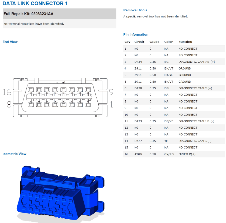
Pin assignments (full 16-cavity table; "N0" entries are unpopulated):

    Cav  Circuit  Gauge   Color    Function
    ---  -------  ------  -------  ------------------------------------
     1   N0       --      NA       NO CONNECT
     2   N0       --      NA       NO CONNECT
     3   D434     0.35    BG       DIAGNOSTIC CAN IHS(+)
     4   Z911     0.50    BK/YE    GROUND
     5   Z911     0.50    BK/VT    GROUND
     6   D428     0.35    BG       DIAGNOSTIC CAN C(+)
     7   N0       --      NA       NO CONNECT
     8   N0       --      NA       NO CONNECT
     9   N0       --      NA       NO CONNECT
    10   N0       --      NA       NO CONNECT
    11   D433     0.35    BG/YE    DIAGNOSTIC CAN IHS(-)
    12   N0       --      NA       NO CONNECT
    13   N0       --      NA       NO CONNECT
    14   D427     0.35    YE       DIAGNOSTIC CAN C(-)
    15   N0       --      NA       NO CONNECT
    16   A900     0.50    GY/RD    FUSED B(+)

The CAN-C diagnostic pair (pins 6 / 14) is what every ISO 15765 OBD-II
scanner expects -- this is the standard. The CAN-IHS diagnostic pair
on pins 3 / 11 is the manufacturer-discretionary usage; FCA /
Stellantis runs the body-bus diagnostic side over those two pins
specifically on this platform. Standard OBD-II tools won't talk to
the IHS side, but DIY harness work over the DLC absolutely can if
both pairs are wired through.

Wire-color mapping to follow:

    D427 (YE)        CAN-C diagnostic (-)
    D428 (BG)        CAN-C diagnostic (+)
    D433 (BG/YE)     CAN-IHS diagnostic (-)
    D434 (BG)        CAN-IHS diagnostic (+)

All four of these conductors land on the SGW (D427/D428 on C1 pins
10/3, D433/D434 on C2 pins 7/2) -- so every byte that arrives at the
DLC is filtered before reaching the in-vehicle trunks.
SGW connector C1 (12-pin) — CAN-C + ignition / ground
Part numbers:
    Full repair kit:      68080557AA
    Terminal repair kit:  68316921AA  (0.64mm Female Unsealed Tin,
                                       18ga, qty 10)

End view (connector facing you):

           pin 6           pin 1
           pin 12          pin 7
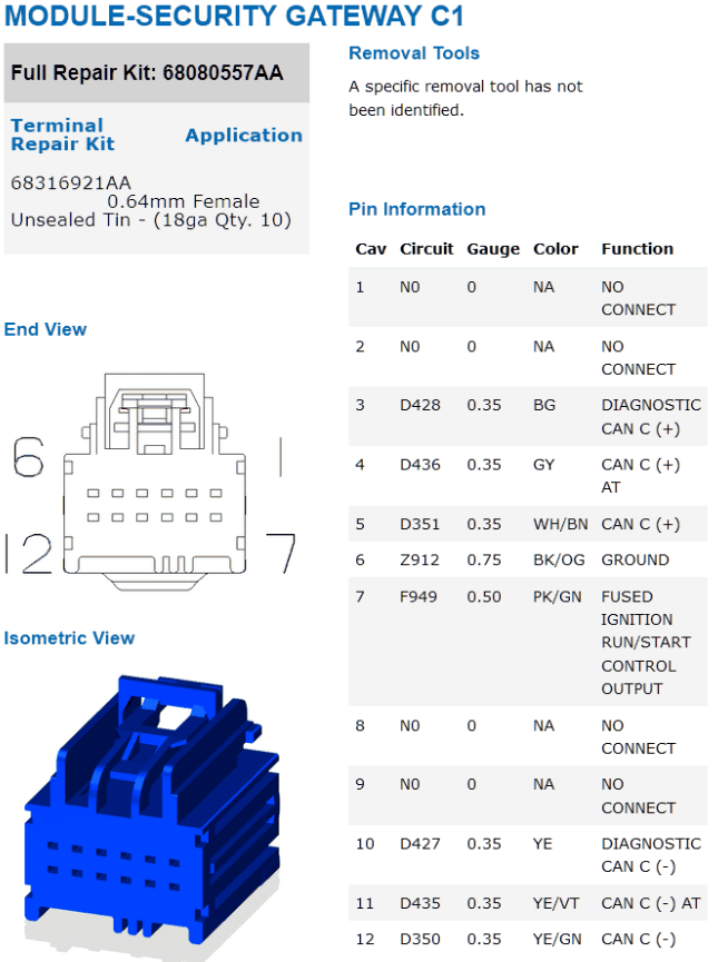
Pin assignments:

    Cav  Circuit  Gauge   Color    Function
    ---  -------  ------  -------  -------------------------------------
     1   N0       --      NA       NO CONNECT
     2   N0       --      NA       NO CONNECT
     3   D428     0.35    BG       DIAGNOSTIC CAN C(+)         <-- from DLC1 pin 6 / 14 pair
     4   D436     0.35    GY       CAN C(+) AT                 --> to "AT" trunk
     5   D351     0.35    WH/BN    CAN C(+)                    --> to primary vehicle trunk
     6   Z912     0.75    BK/OG    GROUND
     7   F949     0.50    PK/GN    FUSED IGNITION RUN/START CONTROL OUTPUT
     8   N0       --      NA       NO CONNECT
     9   N0       --      NA       NO CONNECT
    10   D427     0.35    YE       DIAGNOSTIC CAN C(-)         <-- from DLC1 pin 6 / 14 pair
    11   D435     0.35    YE/VT    CAN C(-) AT                 --> to "AT" trunk
    12   D350     0.35    YE/GN    CAN C(-)                    --> to primary vehicle trunk

Three distinct CAN-C pairs on this single connector:

    pins  3 / 10  -- diagnostic side  (D428 / D427)
    pins  4 / 11  -- "AT" trunk       (D436 / D435)
    pins  5 / 12  -- primary trunk    (D351 / D350)

The split between the primary trunk (5/12) and the "AT" trunk (4/11)
is the SGW's physical separation of post-gateway traffic into two
downstream segments. Powertrain-side modules (PCM, ABS, ESP, MGU,
BPCM) tend to land on the primary trunk; body-adjacent modules
(radio, Emergency Assistance, body-domain stuff) tend to land on the
"AT" trunk. Both are post-filter; the split is for fault-isolation
and routing, not policy.
SGW connector C2 (8-pin) — CAN-IHS + power / ground
Part numbers:
    Full repair kit:      68496366AA
    Terminal repair kit:  68316921AA  (same as C1: 0.64mm Female
                                       Unsealed Tin, 18ga)

End view (connector facing you):

           pin 4           pin 1
           pin 8           pin 5
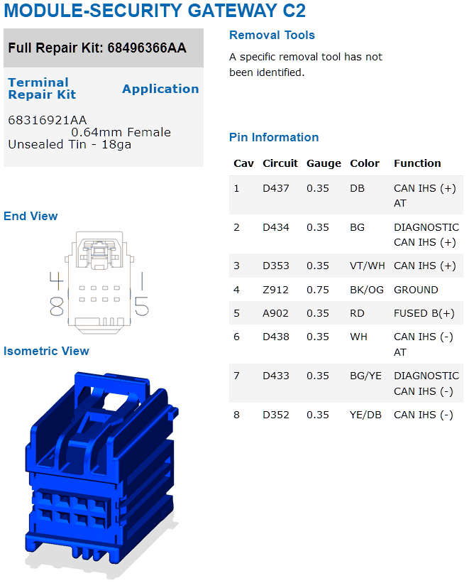
Pin assignments:

    Cav  Circuit  Gauge   Color    Function
    ---  -------  ------  -------  ------------------------------------
     1   D437     0.35    DB       CAN IHS(+) AT             --> to "AT" trunk
     2   D434     0.35    BG       DIAGNOSTIC CAN IHS(+)     <-- from DLC1
     3   D353     0.35    VT/WH    CAN IHS(+)                --> to primary IHS trunk
     4   Z912     0.75    BK/OG    GROUND
     5   A902     0.35    RD       FUSED B(+)
     6   D438     0.35    WH       CAN IHS(-) AT             --> to "AT" trunk
     7   D433     0.35    BG/YE    DIAGNOSTIC CAN IHS(-)     <-- from DLC1
     8   D352     0.35    YE/DB   CAN IHS(-)                --> to primary IHS trunk

Same three-pair pattern as C1, just on a smaller connector and for
the lower-speed body bus:

    pins  2 / 7   -- diagnostic side  (D434 / D433)
    pins  1 / 6   -- "AT" trunk       (D437 / D438)
    pins  3 / 8   -- primary IHS trunk (D353 / D352)

C2 has its own independent ground (Z912) and B(+) feed (A902) so the
SGW continues to power-up independently of the C1-side ignition feed
-- the IHS-side filter logic stays alive even when the ignition is
off, which is what allows the SGW to enforce policy on a sleeping bus
and on RKE-driven IHS wakes (see $2D3 NM-wake
section above).
Vehicle-side CAN-C trunk splices
    Splice       Role
    --------     ----------------------------------------------------
    S2800        Main-trunk splice  (multi-module fan-out)
    S2801        Main-trunk splice
    S2802        Main-trunk splice
    S2803        Main-trunk splice
    S17150       eTorque-branch splice  (EPT-specific)
    S17151       eTorque-branch splice  (EPT-specific)

The S28xx splices are the natural taps for probing the main CAN-C
trunk; the S171xx splices are eTorque-only and absent on non-eTorque
trims.  Wire identifiers on the trunk are D435 / D436 (the "AT"
pair) and D350 / D351 (the primary pair) -- distinct from the
diagnostic-side D427 / D428 pair, which is how you tell pre-SGW vs
post-SGW wiring at a glance behind the glovebox.
eTorque (EPT) branch
    Module                  Connector    Pins        Wire IDs       Colors
    ---------------------   ----------   --------    -----------    --------
    Powertrain Control      C1           12, 13      D662 / D672    0.50 WH/DB, WH/BU
    (PCM, eTORQUE variant)
    Motor Generator Unit    -            4, 10       D630 / D629    0.35 OG/WH, YE
    Battery Pack Control    C1           3, 4 +      D662 / D672    0.35 WH/DB, WH/BU
    Module (BPCM)                        5, 11

"EPT" on the wire labels = ELECTRIC POWERTRAIN. These connections only
exist on eTorque-equipped trims (2.0L turbo eTorque, 3.6L Pentastar
eTorque on JL/JT). On non-eTorque vehicles the BPCM / MGU don't exist,
the wires don't run, and the PCM has only its normal CAN-C(+)/(-) pair
(no -EPT suffix).
Trim-variant routing (a real gotcha)
Several downstream wire colors split by trim. The diagram shows
EXCEPT EXPORT vs EXPORT and PREMIUM vs BASE variants of D435/D436
running to slightly different terminations:

    EXCEPT EXPORT  -- North American + most ROW markets
    EXPORT         -- export-spec trim (different harness routing)
    PREMIUM        -- premium audio / equipment package
    BASE           -- base audio / equipment package

Same logical bus, same message IDs, same protocol — but the wire
identifier (D435 vs D436, vs trim-specific variants) on a given pin
can differ across trims. A capture taken on a Premium-trim JL Wrangler
won't have wire labels identical to the same capture on a Base-trim
JT Gladiator. Bus traffic identical; harness identifiers not.

Implication for harness-side debugging: don't assume that "wire D435
at module X" on one diagram excerpt is the SAME conductor as "wire
D435 at module X" on a different-trim diagram. The bus signal at the
ECU pin is identical; the wire-label database differs.
[ TIPM / TIPMCGW — the bus gateway ]
The TIPM (Totally Integrated Power Module), or TIPMCGW on platforms that include
the Central Gateway, sits between CAN-C and CAN-IHS. It processes and selectively
re-broadcasts messages across the boundary, so the same logical event — an
unlock command, an ignition state change, a security-system trigger — can be
observed on both buses even though it originated on only one of them.

This is why payload size is a useful heuristic for "where did this actually come
from" when the same ID shows up on both buses (see topology note above).
[ Message ID $1C0 — Remote Lock / Unlock (RKE) ]
$1C0  (0x1C0 / 448 decimal)

On the FCA CAN bus, $1C0 lives in the body-control message area alongside
$1C8 and $291, but each of those IDs carries a distinct signal — $1C0
is the actual Remote Lock / Unlock command broadcast (RKE / body control),
typically generated when a key fob lock/unlock command is processed and
originating from the Body Control Module (BCM) or the RF Hub / Wireless
Control Module. $291 in the same neighbourhood carries lighting state, NOT
RKE (see #id-291 below for that one's decode).

Natural home is CAN-IHS, since locks and RKE are interior body functions. If
you observe $1C0 on CAN-C as well, that is almost certainly the TIPM/TIPMCGW
gateway re-broadcasting it for modules on that bus that need to react — e.g.
unlock-on-approach interactions with powertrain or security state.

New messages are sent every ~100 ms while the vehicle is awake; the payload
contains an ID byte representing the last fob command (or an idle-state ID
when no command was received). When the vehicle enters sleep mode, $1C0 stops
broadcasting until the vehicle wakes.

This is the same ID consumed by the Remote_WiFi.sh
script on the parent page — it sniffs $1C0 for fob-driven lock/unlock events
and uses the double-unlock sequence as a covert trigger for the Pi's WiFi radio.

Observed 6-byte payloads on the JEEP platform Remote_WiFi.sh was developed
against (byte 0 = command code, byte 3 = active/idle flag):

    1C0#21 00 00 90 00 00      Lock
    1C0#23 00 00 90 00 00      1st Unlock
    1C0#24 00 00 90 00 00      2nd Unlock     (double-tap)
    1C0#00 00 00 80 00 00      Idle           (no recent command)

Other bytes appear to carry fob ID / button-hold metadata but have not been
positively identified on this platform — see caveats below before assuming
this byte map holds for your year/model.

For the wiring side (BCM / RF-hub / door-lock actuator interconnect), see
VEHICLE-THEFT-SECURITY-SYSTEM.pdf in the
JL wiring-diagram pack.
[ Message ID $25D — Radio mute state (CAN-C) ]
$25D  (0x25D / 605 decimal)  —  CAN-C

Broadcast by the radio head unit while the vehicle is awake. Carries the
current MUTE state of the audio system in byte 3 (zero-indexed):

    byte 3   0x00 = unmuted (audio playing through speakers)
             0x03 = muted

Other bytes have not been decoded on this platform; observed frames look
like  $25D  XX XX XX 00 XX XX XX XX  with byte 3 varying in lock-step
with the mute toggle.

The toggle command itself (steering-wheel MUTE button) is NOT sent on
$25D. It rides on the wake bus as

    $2D3  07 00 01 00 00 00 00 00

— same arbitration ID as the standard NM wake frame, with byte 2 = 0x01
instead of 0x00. The radio treats that frame as a hardware mute-button
press, toggles its internal state, and re-broadcasts the new value on
$25D. Full $2D3 byte map at #id-2d3 below. See
mute.sh for the read-then-toggle pattern,
including the retry-on-bus-quiet wake-frame escalation when no $25D
traffic is observed within the listen window.

PLATFORM NOTE: $25D appears in the
candidate-IDs section below with a
completely different meaning observed on JL Wrangler — locker request
command codes (0x23 = rear, 0x13 = front+rear, 0x43 = unlock both, all
in byte 0). The radio-mute decode above is from a different FCA platform.
FCA reassigns IDs across platforms / model years, so the same ID can
carry entirely different semantics on a different vehicle. Verify on
YOUR vehicle before trusting either decode.
[ Message ID $2D3 — NM wake / center-dash button events (CAN-IHS) ]
$2D3  (0x2D3 / 723 decimal)  —  CAN-IHS

Network Management (NM) frame.  ECUs in low-power state monitor $2D3
to know when to wake up; once an ECU sees a frame on this ID it
transitions from sleep to operational and starts servicing the rest
of the bus.  The same arbitration ID also carries center-dash button
events — the button bitmap rides in byte 2.

Observed payloads:

    $2D3  07 00 00 00 00 00 00 X0     NM wake          ("no button")
    $2D3  07 00 01 00 00 00 00 00     wake + MUTE press

    byte 0   = 0x07         NM frame type / source identifier
    byte 1   = 0x00
    byte 2   = button bitmap
                 0x00 = no button (pure NM wake)
                 0x01 = MUTE pressed
                 other values not yet observed on this platform but
                 likely follow the same one-bit-per-button pattern
                 (volume up/down, source, scan, etc.)
    bytes 3-6 = 0x00
    byte 7    high nibble = arbitrary (BCM ignores it for routing,
                            but a random value per invocation
                            defeats stuck-button detection in some
                            firmware versions — see wake.sh)
              low  nibble = 0x0 (reserved / unobserved)

USAGE PATTERNS

    Pure wake before a sensitive operation:
        cansend can0 2D3#0700000000000000
    or, with random byte-7 high nibble to look like fresh activity:
        cansend can0 2D3#07000000000000${RND}0

    Button-press emulation (mute):
        cansend can0 2D3#0700010000000000

The 3rd_brakelight.sh / horn.sh / 3honk.sh UDS scripts on the parent
page issue a pure-wake variant of this frame before opening their
diagnostic session, because UDS commands on a sleeping ECU silently
drop.  The mute.sh script uses the
button-press variant (byte 2 = 0x01) as the actual mute toggle, since
the radio listens for the same hardware button signal the steering
wheel emits.  The wake.sh tiny helper
is just a one-shot version of the pure-wake send with a fresh random
byte-7 nibble on every call.

PLATFORM NOTE
   The $2D3 frame and its NM-wake role are widely shared across FCA /
   Stellantis platforms.  The button-bitmap byte 2 interpretation is
   more variable -- the only positively-decoded button on the JEEP
   platform mute.sh was developed against is the MUTE button (0x01).
   Other button codes are sniff-and-discover territory.
[ Message ID $328 — EVIC music-info text (CAN-IHS) ]
$328  (0x328 / 808 decimal)  —  CAN-IHS

The radio head unit broadcasts $328 to update the three text lines of
the EVIC music-information page (the metadata region of the cluster
display between the speedometer and tachometer). Each "page update" is
a sequence of $328 frames followed by a single all-zero $328 terminator
frame that commits the new lines.

Per-frame layout for a text payload:

    328  <line>0   <seq><func>   c0 c1 c2 c3 c4 c5

    byte 0  high nibble = remaining-frames counter, counting DOWN from
            (total_frames - 1) to 0.  So a 4-frame payload ships as
            byte 0 = 0x30, 0x20, 0x10, 0x00 in order.  Low nibble = 0.
    byte 1  high nibble = 4 for the FIRST frame of a string, 0 for
                          every continuation frame (sequence marker).
            low  nibble = function -- which of the three text lines:
                          1 = input name        (top line)
                          2 = artist            (middle line)
                          3 = title             (bottom line)
    bytes 2-7  three characters, encoded as UTF-16BE pairs:
                 00 c0   00 c1   00 c2
               where each high byte is 0x00 and each low byte is the
               ASCII code of one character.  Strings are right-padded
               with 00 00 pairs to a multiple of three characters.

Terminator (all bytes = 0x00) commits the lines to the display:

    328  00 00 00 00 00 00 00 00

Without the terminator the EVIC keeps showing the previous text.

The radio also natively broadcasts $328 frames whenever a real audio
source updates — SiriusXM track changes, Bluetooth metadata updates,
USB next-song presses. Hijacking the message means temporarily masking
whatever the radio was about to display; once the user changes track
or pauses the radio refreshes its own state and overwrites your text.

See evic.sh for the encoder. The script
takes a line number (1/2/3) and a free-form string, encodes the
UTF-16BE pairs, and emits the frame sequence with the right counter
and seq-marker bytes.
[ Message ID $291 — Headlights / turn signals / interior lighting (CAN-IHS + CAN-C) ]
$291  (0x291 / 657 decimal)  —  CAN-IHS  (re-broadcast on CAN-C
                                              by the TIPM/CGW gateway)

Native home is CAN-IHS — $291 is body-control state (lights are body
functions, not powertrain).  But the TIPM/CGW gateway re-broadcasts
this ID onto CAN-C for modules on that bus that need to react to
light changes, which means $291 is observable on EITHER bus on most
FCA platforms.  Scripts on this site disagree on which bus to read
from (backlight.sh uses can1=CAN-IHS in its labelling; lights.sh
uses can1=CAN-C) -- both work in practice because the gateway
mirrors the frames.  Use whichever bus is most convenient for your
wiring.

Broadcasts the current state of the headlight stalk and interior
lighting controls while the vehicle is awake. Five independent
signals decoded so far, each in its own byte of the 8-byte payload:

    byte 2   Running lights      LOW NIBBLE carries the flag:
                                  0x_0 = off
                                  0x_1 = on
                                  0x_3 = on (alternate code, possibly
                                          auto-headlight-controlled
                                          mode)
                                  High nibble carries other state we
                                  haven't fully decoded; observed
                                  values include 0x00 and 0x10.
                                  Practical check: `byte2 & 0x0F`
                                  matches 1 or 3 -> running lights on.
                                  See backlight.sh
                                  for an in-the-wild low-nibble test.
    byte 3   Turn signals /     HIGH NIBBLE carries the blinker state:
             hazards              0x0_ = no blinker
                                  0x4_ = left blinker
                                  0x8_ = right blinker
                                  0xC_ = hazards (both)
                                  Low nibble not yet decoded.
                                  See lights.sh
                                  for a file-as-flag exporter.
    byte 5   Cabin lights        0x00 = off
                                  0x01 = on
    byte 6   Interior dimmer     0x22 = lowest brightness
                                  0xC8 = highest brightness
                                  (linear 0x22..0xC8 = 34..200 dec,
                                   ~166-step display brightness range)
    byte 7   Headlights          0x00 = off
                                  0x02 = low beam
                                  0x04 = high beam

Bytes 0, 1, 4 not yet decoded — likely carry additional lighting
state (fog lights, auto-headlight mode, daytime running lights as a
distinct signal, etc).

Notable combinations:

    running=0, headlights=0    all off
    running=1, headlights=0    parking / DRL / running lights only
    running=1, headlights=2    low beam (running automatically on)
    running=1, headlights=4    high beam (running automatically on)

That is: $291 byte 7 carries the BEAM state, and byte 2 carries the
running-lights state separately. Both being non-zero is the normal
"headlights on" condition; running=1 alone is parking-lights-only.

Relationship to $1C0 / $1C8: $291 sits alongside the RKE messages
in the body-control area of CAN-IHS, but it specifically carries
lighting state — not RKE. The "$1C0 / $1C8 / $291 message
group" framing in older notes is overly broad; treat $291 as a
separate body-control broadcast on its own.

Potential collision: the candidate-IDs MEDIUM table below lists
$214 as a headlight-and-turn-signal candidate carrying bit flags.
$291 is the authoritative entry for headlight beam state on this
platform; $214 may be a related but different signal — the BCM
sometimes broadcasts switch position separately from the actual
output state. Investigate further if your application cares about
the distinction.
[ Message ID $122 — Ignition / virtual key state (CAN-IHS) ]
$122  (0x122 / 290 decimal)  —  CAN-IHS only

Broadcast every ~100 ms while the vehicle is awake; carries the virtual
ignition switch state (OFF / ACCESSORY / RUN / START). The vehicle stops
sending $122 entirely when it enters sleep mode — absence of $122 is the
sleep-state signal.

The Blackbox_monitor.sh script
treats the payload as a single big-endian integer and uses bit 26
(0x04000000) as the run-state flag:

    payload >= 0x04000000   ⇒  RUN / START   (engine running, ACC + RUN)
    payload <  0x04000000   ⇒  OFF / ACCESSORY

That bit-26 threshold is sufficient to drive on/off automation (start log
on RUN, terminate log on OFF). For finer-grained discrimination, the
first two bytes of $122 carry specific state codes:

    bytes 0-1 hex   state
    -------------   -----
    0000 / 0001     Off
    0301 / 0302     Kill        (ignition explicitly killed)
    0502 / 1502     Accessory
    4501            Start       (starter cranking, key-driven)
    5D01            Crank       (crank in progress, possibly
                                 remote-start related)
    4401            Remote-Run  (engine running from a remote start)
    0402            Run         (engine running, normal key-driven)

These codes are decoded by the
log_reader.sh replay tool and
mapped to short human-readable labels (Off / Kill / Acc / Strt / Crnk
/ RRun / RAcc / Run / Unk) for one-line-per-tick rendering. The
"RAcc" label is a derived state: byte 0-1 is 4401 (Remote-Run) but
RPM is zero, meaning the engine isn't actually turning -- accessory-
mode equivalent during remote start.
[ Message ID $077 — Engine / vehicle state (CAN-C) ]
$077  (0x077 / 119 decimal)  —  CAN-C

Engine / vehicle running-state broadcast on CAN-C. Bytes 0-1 form a
16-bit state code; observed values on the JEEP platform:

    0x0422   Engine running (most common code)
    0x4421   Engine running (alternate / mode-dependent)
    0x5D21   Remote start in progress
    < 0x0400  Vehicle off / accessory / pre-crank
    > 0x0399  Vehicle on  (engine may or may not be running)

The script uses these thresholds to fire callbacks:

    state < 0x0400               vehicle off / engine shutdown
    state >= 0x0400              vehicle powered on
    state in {0x0422, 0x4421}    engine running (fires enginestarted
                                  once per cold start)

Bytes 2-7 of $077 aren't decoded by the current
autocollect.sh script; they
likely carry additional sub-mode or transmission state. Candidate
follow-on candump-diff exercise: trigger known states (key-on / start
/ remote start / shift through PRNDL / kill engine) and watch which
bytes beyond 0-1 change.

Relationship to $122: $077 and $122 both encode "is the engine
running?" but on different buses and with different formats. $122 is
on CAN-IHS and uses a bit-26 threshold across the full 32-bit
payload (see #id-122 above). $077 is on CAN-C
and uses specific 16-bit state codes. Either signal is sufficient
for on/off automation; the framework-vs-recorder choice is more
about how many hook points you need than which signal you watch.

Pre-2018 note: a script using $077 byte-pattern comparison via bash
`-gt` / `-lt` against the raw hex string will crash on any state
containing A-F (like 0x5D21). The legacy autocollect.txt has a
hard-coded `5D21 -> 5555` workaround; the tidied autocollect.sh
converts via $((16#$state)) so all hex values compare correctly.
[ Message ID $08B — Individual wheel speeds (CAN-C) ]
$08B  (0x08B / 139 decimal)

Broadcast on CAN-C every 1/50th of a second (20 ms cadence). Carries
the live speed of each of the four wheels in MPH * 20 — raw integer,
no long-period averaging, just the most recent ABS-sensor reading the
ESC module has on hand.

Dividing the raw value by 20 yields MPH with a resolution of 0.05 MPH
per count, which is finer-grained than anything the dashboard
speedometer renders. Four wheel slots fit in the 8-byte payload as
2-byte big-endian fields:

    bytes 0-1   front left   wheel speed   (raw / 20 = MPH)
    bytes 2-3   front right  wheel speed   (raw / 20 = MPH)
    bytes 4-5   rear  left   wheel speed   (raw / 20 = MPH)
    bytes 6-7   rear  right  wheel speed   (raw / 20 = MPH)

Useful for ABS / traction-control work, slip-angle inference, and any
case where you want per-corner motion rather than the gateway's already-
averaged value.
$08B vs $340 — primary speedometer mismatch
When the $08B per-wheel readings are compared against the vehicle's
primary speedometer source (CAN-IHS $340,
which the transmission module broadcasts and the dashboard renders),
the dashboard reads consistently HIGHER than the wheels — on the
order of 1–2 MPH, persistently, not just a transient blip.

That's not measurement noise. The dashboard speedometer is intentionally
biased upward across most automakers to comply with regulations
(UNECE R39, FMVSS 101 in spirit) that forbid an under-reading speedo
but allow over-reading. The bias is typically 1–3 MPH at highway
speeds.

Implication for tooling: if you want the TRUE wheel speed for telemetry,
slip calculations, or comparison against GPS, prefer $08B over $340.
If you want what the driver SEES, use $340. Don't blend the two
sources into a single "vehicle speed" reading without picking which
semantic you mean.
[ Message ID $2C2 — Battery voltage (CAN-IHS) ]
$2C2  (0x2C2 / 706 decimal)

Broadcast frequently on CAN-IHS while the vehicle is awake. Byte 2 of
the 8-byte payload encodes battery voltage in tenths-of-a-volt:

    byte 2   battery voltage   raw / 10 = volts
                               (e.g. 0x78 = 120 = 12.0V, 0x86 = 13.4V)

Other bytes carry additional power-distribution data the community
has not fully decoded; partial captures suggest at least one bit
flips when the alternator is producing vs draining. Capture-and-diff
with the engine off vs running is the easiest way to map those.

If the entire payload reads as 0xFF * 8, the bus has either gone to
sleep or the BCM hasn't re-broadcast since a wake event — treat
that as a sentinel and either wake the bus (one $2D3 NM-wake frame)
or wait for the next natural transmission.
Worked example — reading battery voltage with the on-site battery.sh helper:
    candump   can0 2C2 # 14 B3 78 00 00 00 00 00
                                \/
                                |
                                +-- byte 2 = 0x78 = 120 decimal

    Decode    raw / 10 = 120 / 10 = 12.0 V

    Script    $ ./battery.sh
              12.0 vdc
The script uses a 2-second candump window with an ID filter (candump -L can0,02C2:0fff), retries once after sending a $2D3 NM-wake frame if the bus is asleep, and treats an all-FF payload as a hard error. Useful for cron-driven health checks of a parked vehicle or as a quick "is the battery sagging under load?" probe during ignition / accessory transitions.
[ Message ID $350 — Vehicle clock / RTC ]
$350  (0x350 / 848 decimal)

Broadcast once per second on both CAN-C and CAN-IHS while the vehicle is
awake. Carries the dashboard clock as raw hex (NOT BCD), one field per byte:

    byte 0   seconds              (0x00..0x3B)
    byte 1   minutes              (0x00..0x3B)
    byte 2   hours                (0x00..0x17)
    bytes 3-4  year               (big-endian, e.g. 0x07E7 = 2023)
    byte 5   month                (0x01..0x0C)
    byte 6   day                  (0x01..0x1F)

A payload of all 0xFF means the clock has never been initialized (vehicle
disconnected from battery, or set-from-radio has not run). The
getVehicleTime.sh script uses this
as an error sentinel.

Because the message ID and payload format are stable across platforms (the
dashboard clock has to render somewhere), $350 is one of the more reliable
"is this bus even alive" probes during initial reverse-engineering.
[ Message ID $358 — Compass heading ]
$358  (0x358 / 856 decimal)

Broadcasts the dashboard compass heading as an 8-position cardinal
direction code in the LOW NIBBLE of byte 0:

    byte 0 nibble:
        0x0  N    (North)
        0x1  NE   (Northeast)
        0x2  E    (East)
        0x3  SE   (Southeast)
        0x4  S    (South)
        0x5  SW   (Southwest)
        0x6  W    (West)
        0x7  NW   (Northwest)
        0xF  unknown / no fix (compass not yet calibrated, or
              vehicle disconnected from the magnetometer)

The high nibble of byte 0 and the rest of the payload not yet decoded
— likely carries finer-grained heading, calibration state, or
tilt-compensation data. The 8-direction code is sufficient for the
"which way is the car pointing" display the dashboard compass icon
shows, but a real-degree heading would need deeper decode.

Decoded by the log_reader.sh
replay tool to render the DIR field on each tick line.
[ Message ID $3E0 — Vehicle Identification Number (VIN) ]
$3E0  (0x3E0 / 992 decimal)  —  CAN-IHS

Broadcasts the vehicle's 17-character VIN across three sequential
frames at roughly 0.1 s intervals. Each frame carries:

    byte 0      sequence id  (0x00, 0x01, or 0x02)
    bytes 1-7   seven VIN characters as raw ASCII (in hex)

The 17 VIN characters don't divide evenly into 7-byte payloads
(7 + 7 + 3 = 17), so the third frame's trailing bytes are 0x00 padding.
Strip the nulls during reassembly.

Frames may arrive out of order on a busy bus — assemble by
sequence id, not arrival order. Example capture (CAN-IHS, awake
vehicle):

    can0 3E0#00 31 43 36 4A 4A 54 41    "00 1C6JJTA"   (frame 0, chars 0-6)
    can0 3E0#01 47 35 4C 34 30 30 32    "01 G5L4002"   (frame 1, chars 7-13)
    can0 3E0#02 33 34 35 00 00 00 00    "02 345"       (frame 2, chars 14-16 + pad)

Reassembled VIN: 1C6JJTAG5L4002345 (17 characters).

ISO-standard alternative: UDS Service 0x22 (ReadDataByIdentifier) on
DID 0xF190 returns the VIN via the diagnostic protocol on whatever
module owns it. Broadcast on $3E0 is easier when available
(no session control, no $7E0 / $7E8 etc.); UDS is the right fallback
when the platform doesn't broadcast.

Compatibility note: some older / non-Wrangler FCA platforms may
broadcast VIN on $380 instead of $3E0. Always candump on YOUR vehicle
to confirm before scripting. The
getVIN.sh script's CAN_ID variable is
the one knob to change if your VIN lives elsewhere.
[ UDS over CAN-C — service path used by 3rd_brakelight.sh ]
UDS (Unified Diagnostic Services, ISO 14229) rides on CAN-C with a
request/response framing completely different from the broadcast-style
messages above. Every request gets a positive or negative response from
the target ECU.

The 3rd_brakelight.sh script uses
the following sequence to toggle the cargo-area / 3rd brake light:

    1.  NM wake frame on $WAKE_BUS.  cansend can0 2D3#0700000000000000
        Wakes ECUs out of low-power
        sleep before the diagnostic
        session begins below.

    2.  Enter Extended Diagnostic    cansend can1 620#0210030000000000
        Session (Service 0x10,                     |  |  +- subfn 0x03
        sub-function 0x03).                        |  +---- service 0x10
                                                   +------- PCI len = 2

    3.  TesterPresent keepalive,     cansend can1 620#023E800000000000
        sent every ~2 seconds from                 |  |  +- sub 0x80
        a background loop so the                   |  |     (suppress positive
        ECU's S3 timer (typically                  |  |     response, quieter)
        ~5 seconds) never drops our                |  +---- service 0x3E
        session.                                   +------- PCI len = 2

    4.  IOControlByIdentifier        cansend can1 620#052FD1B303010000
        (Service 0x2F), DID                        |  |    |  |  +-- state
        $D1B3 (3rd brake light),                   |  |    |  +----- control byte
        control 0x03 (short-term                   |  |    +-------- DID lo
        adjustment), state 0x01 (ON):              |  +------------- DID hi / svc
                                                   +---------------- PCI len = 5

    5.  Turn it OFF with state 0x00: cansend can1 620#052FD1B303000000

    6.  On exit / Ctrl+C, hand       cansend can1 620#042FD1B300000000
        control back to the ECU                    |  |    |  +----- control 0x00:
        (returnControlToECU). Note:                |  |    |         returnControlToECU
        NO state byte -- this                      |  |    +-------- DID lo
        request is one byte shorter                |  +------------- DID hi / svc
        than the shortTermAdjustment.              +---------------- PCI len = 4

Notable:

  - $2D3 on the wake bus is a Network Management (NM) frame, not UDS.
    Full byte map at #id-2d3.
  - $620 is the UDS REQUEST arbitration ID for the BCM; this ECU's
    RESPONSE arrives on $504. The request/response delta isn't a fixed
    constant on FCA platforms — each module has its own pair, you
    discover them by triggering an interaction from a known-good UDS
    tool (JScan, wiTECH, etc.) while watching candump. See
    Reverse Engineering UDS with JScan
    for the technique.

  - Positive response service byte = request service byte + 0x40. So
    request 0x10 (DiagnosticSessionControl) yields response 0x50;
    request 0x2F (IOControlByIdentifier) yields 0x6F; request 0x22
    (ReadDataByIdentifier) yields 0x62; request 0x31 (RoutineControl)
    yields 0x71. Negative responses are always 0x7F followed by the
    original service byte and a one-byte NRC (e.g. 0x33 =
    securityAccessDenied, 0x12 = subFunctionNotSupported).

  - Service 0x2F (IOControlByIdentifier) is your knob for forcing
    actuators via diagnostics. Service 0x22 (ReadDataByIdentifier) is
    the safe read-only equivalent — always read a DID via 0x22
    before any 0x2F write so you know how to undo your change. Service
    0x31 (RoutineControl, sub 0x05 start / 0x02 stop / 0x03 results)
    is the heavier-weight cousin: starts a routine on the target ECU
    that runs as long as the diagnostic session stays open. Used by
    2k.sh to hold engine RPM via the ECM.

  - Two cleanup models for actuator writes:
        TOGGLE-AND-RELEASE   IOControl ON, then explicitly IOControl
                             OFF + returnControlToECU on exit. Used
                             by horn.sh / 3rd_brakelight.sh (with a
                             SIGINT trap to cover Ctrl+C).
        HOLD-VIA-TESTERPRESENT
                             Start a routine, then keep the session
                             alive with TesterPresent. Stop pinging
                             and the session times out, which
                             automatically releases the routine. No
                             explicit cancel command. Used by 2k.sh.

  - Session sub-functions seen on this platform:
        0x01  defaultSession            (always available)
        0x03  extendedDiagnosticSession (BCM honor; horn / brake)
        0x92  Chrysler manufacturer-    (ECM honors; RPM hold via
              specific session         RoutineControl)

  - The same walkthrough works verbatim for any IOControl- or
    RoutineControl-addressable target on the same ECU. Known module
    ID pairs and DIDs / routine IDs on this JEEP platform:

        $620 / $504  Body Control Module (BCM)
            $D0AD  horn          (see horn.sh)
            $D1B3  3rd brake     (see 3rd_brakelight.sh)
            ...    40+ more BCM IOControl DIDs (turn signals, fog
                   lights, low/high beams, marker / park / reverse
                   lamps, wipers, washer, door locks, courtesy /
                   reading / footwell lights) on JL Wrangler / JT
                   Gladiator. Full catalog at UDS
                   Write Operations: Known writable targets.

        $783 / $503  HVAC Module
            $D020  battery voltage (read-only via Service 0x22,
                   8-bit value = volts * 10)

        $7E0 / $7E8  Engine Control Module (ECM)
            (OBD-II 11-bit IDs, NOT FCA-internal -- different
             namespace from the BCM / HVAC pairs above)
            Routine ID 0x07D0 = 2000 RPM target via Service 0x31
            sub 0x05 startRoutine. Untested hypothesis: the routine
            identifier IS the RPM value in BE-decimal, so 0x05DC
            would set 1500 RPM, 0x09C4 would set 2500 RPM, etc.
            See 2k.sh.

    Substitute the DID / routine ID — and the module's request/
    response IDs — and you've got a new script. The scaffolding
    (NM wake + Session Control + TesterPresent + actuator command)
    is reusable across all of them. For the cross-script perspective
    on this pattern (cleanup models, service comparison, known
    writable targets, SGW gating, safety rules), see
    UDS Write Operations on FCA /
    Stellantis.
  - Steps 3 and 6 are the safety-correct additions the tidied script adds
    over a naive "loop forever sending 0x2F" implementation. Without
    TesterPresent the session can time out on bus quiet; without
    returnControlToECU the ECU stays in test-controlled state until
    something else writes the DID or the session expires on its own.

Python alternative for UDS work: udsoncan
(referenced in 3rd_brakelight.sh's notes).

UDS over the OBD-II port specifically on 2018+ FCA vehicles is gated by the
Secure Gateway Module — see the
SGW / SGM reference for what gets
through unauthenticated and what doesn't. Direct CAN access via the
13-way connectors behind the glovebox is NOT gated by the SGW, which is
one of the main reasons that access point is useful for research work.
[ Module ID catalog — known UDS endpoints ]
Catalog of UDS arbitration ID pairs observed on the FCA / Stellantis JEEP platform, accumulated from on-vehicle reverse engineering. Tx is the request ID the tester sends; Rx is the response ID the module replies on. The Rx = Tx + offset relationship varies by module (0xBC offset for the 0x6xx range, 0x180 offset for the 0x7xx range, just +0x08 for the OBD-II-standardised 0x7Ex range).
The same module pairs power the script catalog in wid.py, ioid.py, and ecureset.py — if you want to talk UDS to one of these modules from Python, those scripts' MODULE_INFO dict is keyed off this same table.
  Tx     Rx     Bus       Module
  -----  -----  --------  -------------------------------------------
  $47E   $47F   ?         Security Gateway Module           (see SGW guide)
  $620   $504   CAN-IHS   Body Control Module               (BCM -- horn, brake light, etc.)
  $740   $4C0   ?         RF Hub                            (RKE receiver)
  $742   $4C2   ?         Instrument Panel Cluster (IPCM/EVIC)
  $743   $4C3   ?         Tire Pressure Monitoring (TPMS)
  $744   $4C4   ?         Airbag / Occupant Restraint
  $747   $4C7   CAN-C     Anti-lock Braking System (ABS)
  $749   $4C9   ?         Electronic Shifter
  $74A   $4CA   CAN-IHS   Sway Bar                          (Wrangler disconnect; cf. $26F broadcast)
  $74B   $4CB   CAN-C     Drive train FDC
  $753   $4D3   ?         Adaptive Cruise Control (ACC)
  $75A   $4DA   ?         Park Assist
  $762   $4E2   ?         Electric Power Steering (EPS)
  $763   $4E3   ?         Steering Column Module (SCM)
  $783   $503   ?         HVAC                              (battery V at DID $D020)
  $784   $504   ?         Driver Door (?)
  $785   $505   ?         Passenger Door (?)
  $792   $512   CAN-IHS   Unknown
  $794   $514   ?         Central Vision Processing
  $7BC   $53C   ?         Integrated Center Stack Control (CSCM)
  $7BE   $53E   ?         Amplifier
  $7BF   $53F   CAN-IHS   Uconnect Radio Module
  $7E0   $7E8   CAN-C     Powertrain CM / ECM               (2k.sh, obd.sh, obd2.py)
  $7E1   $7E9   ?         Transmission CM (TCM)
  $7E2   $7EA   ?         Hybrid Control Processor
  $7E7   $7EF   ?         Battery Pack Control Module
Notes on the entries:
- SGW at $47E/$47F. The Secure Gateway Module itself responds to UDS. That means there's an authentication / introspection surface on the gateway distinct from "send a request through the gateway." The full SGW guide covers the behaviour at the policy layer; the UDS endpoint here is the direct addressing if you want to talk to the gateway specifically rather than something behind it.
- $74A vs $26F sway bar. $26F is the broadcast request that the steering-wheel sway-bar-disconnect button emits (documented in candidate IDs below); $74A/$4CA is the sway-bar module's UDS interface. Both relate to the same hardware feature but are different addressing schemes (broadcast vs request/response).
- $75A is Park Assist, not PCM. Earlier catalogues on this site (including pre-2026-05 versions of wid.py and ioid.py) labeled $75A as PCM. That was wrong — the Powertrain Control Module is on the OBD-II-standardised $7E0/$7E8 pair (same as ECM; PCM and ECM are different terms for the same physical module on FCA). Reverse-engineering work at this depth on Park Assist hasn't been done on this site.
- $784 / $785 with (?). The labels "Driver Door" and "Passenger Door" are educated guesses based on sequential placement after HVAC ($783) and the door-module convention on other FCA platforms. Not confirmed by direct test.
- $792 unknown. Responds, on CAN-IHS, role unknown. Excellent target for a Service 0x22 DID sweep if you want to discover what kind of module it is.
For module IDs that exist in this table but DON'T have an on-site demo script targeting them, the path to making one is: wid.py + the appropriate module key, plus a Service 0x22 read for discovery first to avoid bricking anything. The 9-rule safety section on the UDS Writes page applies in full.
[ Worked example — Service 0x22 ReadDataByIdentifier on the BCM ]
The walkthrough above used Service 0x2F (IOControlByIdentifier) as the write path that 3rd_brakelight.sh follows. Service 0x22 is the read counterpart — ask an ECU for the value stored under any Data Identifier (DID); no session unlock required for most DIDs. Full read-side architecture (module catalog, DID discovery patterns, ISO-TP framing, SGW pass-through rules) lives on the dedicated UDS Read Operations reference guide; this section walks one read byte-by-byte as a concrete companion example.
Worked example: read DID $0146 (CSM1 — a BCM configurable-security
data field) on a 2021 Jeep Wrangler via the behind-the-glovebox CAN-C
connector, using isotpsend / isotprecv from
can-utils. Two terminals. Terminal 1 sets up the listener
(blocks until a response arrives):
isotprecv -s 620 -d 504 -p 00:00 -P l can1
Terminal 2 sends the request:
echo "22 01 46" | isotpsend -s 620 -d 504 -p 00:00 -P l can1
Terminal 1 prints the response. If the first attempt sees nothing, the
bus was probably asleep — the isotpsend frame itself wakes it, so a
second invocation should succeed. Observed response on the test vehicle:
62 01 46 00 30 76 41 E4 A3 C7 10. Decoded byte-by-byte:
    Request   22 01 46
              \_/  \__/
               |     |
               |     +-- DID = $0146 (CSM1 -- BCM configurable security data)
               +-------- Service 0x22 ReadDataByIdentifier

    Response  62 01 46 00 30 76 41 E4 A3 C7 10
              \_/ \__/ \_____________________/
               |   |              |
               |   |              +-- 8 bytes of payload from DID $0146
               |   +----------------- DID echo (== request DID)
               +--------------------- 0x62 = 0x22 + 0x40 (positive response)
Same +0x40 positive-response rule covered for the 0x2F walkthrough
above: service byte + 0x40 on success, 7F <service> <NRC>
on failure. For example 7F 22 13 would indicate
"incorrectMessageLengthOrInvalidFormat" against the read request;
7F 22 31 "requestOutOfRange" (DID not implemented on this
ECU). isotprecv handles ISO-TP reassembly transparently — the 11
payload bytes above arrive as a single-frame or first-frame +
consecutive-frame pair on the wire, but you see the reassembled
content.
Single-threaded interaction caveat. Unlike broadcast
traffic (where candump and event handlers can multi-thread freely),
direct UDS module interaction needs to be serialised. Two concurrent
isotpsends against the same ECU can interleave at the
wire, the ECU may answer one but not the other, and a separate
listener may pick up the "wrong" response. The standard fix is a
single-threaded gateway pattern: serialise every 0x22 / 0x2F / 0x2E /
0x31 call through one process so requests stay paired with their
responses.
Python equivalent. For the same VIN read implemented with the python-can + python-can-isotp + udsoncan stack instead of can-utils CLI tools, see read_vin_uds.py on the parent page. Same BCM, same DID 0xF190, same request / response on the wire — just scripted in Python with ISO-TP framing and UDS protocol handled by libraries instead of by hand.
Forward-looking notes (jmccorm's research direction for this technique, not yet implemented on this site):
- Single-threaded UDS gateway. Mediates all direct-module traffic; guarantees that responses are routed to the correct caller.
- DID sweep. Walk every identifier from $0000 to $FFFF against a target module and record which ones return a positive 0x62 response. The result is the module's DID map — the basis for a full configuration baseline. An earlier attempt via udsoncan suggested some modules stop cooperating under aggressive sweep rates; rate-limiting and back-off are likely required.
- Vehicle baseline snapshot. Dump all valid DIDs to persistent storage as a known-good configuration backup — restore after experimentation if anything goes sideways. Tazer's "marry" operation does something similar at the platform level.
[ Decoded BCM read-only DIDs ]
BCM DIDs whose payload fields have been decoded (not just verified as "returns 0x62 on read"). As more DIDs get their internal structure mapped, this list grows. Companion to the BCM IOControl DID catalog on the UDS Writes page, which lists the 0x2F-controllable actuators on the same module.
$0146 — CSM1 (BCM configurable security data, 8 bytes)
Used as the worked example in Service 0x22 ReadDataByIdentifier above. Round-trip Service 0x2E write verified by jmccorm against this DID. Internal field semantics not yet mapped — treat as an 8-byte opaque blob whose bit-level meaning is TBD.
$A01A — Oil-change statistics (6 bytes)
Service 0x22 read. Three big-endian 16-bit fields tracking driving metrics since the last oil-change reset on the dash:
    Read DID $A01A
    --------------
    Request:   22 A0 1A
    Response:  62 A0 1A b0 b1 b2 b3 b4 b5
                                \___/ \___/ \___/
                              |     |     |
                              |     |     +-- kilometres since reset (b4 * 256 + b5)
                              |     +-------- hours since reset (b2 * 256 + b3)
                              +-------------- engine revs since reset (b0 * 256 + b1) * 1000
Worked example, captured live from a real vehicle (jmccorm's vehicle,
read via the rid companion to
wid.py with -d decimal output):
  $ rid -d bcm A01A
  13 152 0 38 2 245
Decodes as:
  Engine revolutions: (13 * 256 + 152) * 1000 =  3,480,000 revs
  Hours running:      (0 * 256 + 38)        =          38 hours
  Distance:           (2 * 256 + 245)       =         757 km  (~470 mi)
The "× 1000" multiplier on the revs field is the trick — the BCM stores revs in thousands rather than counting every individual crank rotation (which would overflow a 16-bit counter in roughly an hour of driving). A full 16-bit value here = 65 535 × 1000 = 65.5 million revs before wraparound, which is realistic for typical oil-change intervals.
Equivalent hex view (same payload, no -d flag):
  $25D-style read of $A01A:
      Request:    cansend $UDS_BUS  $REQ#03 22 A0 1A 00 00 00 00
      Response:   $RESP#08 62 A0 1A 0D 98 00 26 02 F5
      Payload:    0D 98 00 26 02 F5
                  └─┬─┘ └─┬─┘ └─┬─┘
                    │     │     └── 02F5h =   757 km
                    │     └──────── 0026h =    38 hours
                    └────────────── 0D98h × 1000 = 3,480,000 revs
Use cases beyond curiosity:
- Verify a service-record claim. A used-vehicle inspection can read this DID to confirm an oil-change history.
- Service interval automation. A Pi reading this every key-on cycle can warn before the OEM dash interval is hit.
- Reverse-engineer the dash "oil reset" sequence. Writing zeros to this DID via Service 0x2E should reset all three counters — if it works, it's the UDS equivalent of the in-dash menu reset. Not verified on this site; would be a clean wid.py demo target.
[ OBD-II over CAN-C — the standardised cousin of UDS ]
OBD-II (SAE J1979 / ISO 15031) is the standardised emissions-diagnostic
protocol every car sold since ~1996 supports. It rides on the same CAN-C
bus and the same $7E0 / $7E8 ECM arbitration-ID pair as UDS, but uses a
different service set:

    Service 0x01  ShowCurrentData       -- live sensor data by PID
    Service 0x02  ShowFreezeFrame       -- snapshot at last DTC
    Service 0x03  ShowDTCs              -- read stored fault codes
    Service 0x04  ClearDTCs             -- clear fault codes (WRITE)
    Service 0x05  TestResults_O2_NonCAN
    Service 0x06  TestResults           -- continuous monitor data
    Service 0x07  ShowPendingDTCs
    Service 0x08  Control               -- on-board system control
    Service 0x09  RequestVehicleInfo    -- VIN, calibration ID
    Service 0x0A  ShowPermanentDTCs

Positive-response convention is identical to UDS: service byte + 0x40.
Service 0x01 requests yield 0x41 responses with the PID echoed in the
next byte and data after. Mode 0x09 multi-frame VIN responses use the
same ISO-TP framing UDS uses.
Practical prerequisites for first-time Mode 01 queries
Two things commonly trip up first-time OBD-II Mode 01 queries on
the JEEP platform:

1. The vehicle must be powered on.  Accessory mode or
   Run/Start with the engine off will pass most queries.  With the
   ignition fully off, the ECM stops responding to $7E0 within a few
   seconds of the bus going quiet -- you'll see no response frame at
   all, not even a Negative Response Code.

2. Send on CAN-C, not CAN-IHS.  Live powertrain data
   only rides the CAN-C bus.  Sending the request frame on the
   CAN-IHS bus produces no response (the ECM isn't listening there).
   On the on-site Pi rig that's normally can1
   (CAN-C, 500 kbps) -- see the primer
   for the can0 vs can1
   naming gotcha.

The request always uses ID $7E0 (ECM functional
request); listen for the response on $7E8 (ECM
physical response).  Padding to 8 bytes is convention but not strictly
required -- can-utils pads automatically when you use cansend's
short-form syntax.
Worked example 1 — read PID 0x0C (Engine RPM) on the ECM:
    Request   can1 7E0 # 02 01 0C 00 00 00 00 00
               \  /   \  /  \/  \/
                |      |    |    |
                |      |    |    +-- PID echoed back in response
                |      |    +------- Service 0x01 ShowCurrentData
                |      +------------ PCI length = 2 (service + PID)
                +-------------------- ECM request ID

    Response  can1 7E8 # 04 41 0C 11 B8 00 00 00
                       \  /  \/  \/  \-+-/
                        |   |   |     |
                        |   |   |     +-- 2 data bytes: 0x11 0xB8
                        |   |   |         = 17, 184 decimal
                        |   |   +-------- PID echo
                        |   +------------ 0x41 = 0x01 + 0x40 (positive)
                        +---------------- PCI length = 4

    Formula (from the OBD-II spec): RPM = ((A * 256) + B) / 4
                                          ((17 * 256) + 184) / 4
                                        = 1134 RPM
Worked example 2 — read PID 0x05 (Engine coolant temperature) on the ECM. This one uses a single-byte data field with an offset-from-40 decode — the kind of thing that's easy to miss if you don't check the PID's decode rule in the spec:
    Request   can1 7E0 # 02 01 05 00 00 00 00 00
                                |
                                +-- PID 0x05 = engine coolant temp

    Response  can1 7E8 # 03 41 05 27 00 00 00 00
                                \/  \-+-/
                                |     |
                                |     +-- 1 data byte: 0x27 = 39 decimal
                                +-------- PID echo (0x05)

    Formula (from the OBD-II spec): coolant_C = A - 40
                                          39 - 40
                                        = -1 °C (about 30 °F — cold-start reading)
The A - 40 offset is shared by every temperature PID in the Mode 01 spec (0x05 coolant, 0x0F intake air, 0x46 ambient air, 0x5C engine oil). It maps the 8-bit unsigned range [0, 255] to the signed Celsius range [-40, +215]. At -40 you'd see the byte read 0; at +215 °C you'd see 0xFF. Anything in between follows the same subtraction.
OBD-II PIDs every modern car supports (selection):

    0x05  Engine coolant temperature   A - 40 = degC
    0x0C  Engine RPM                   ((A*256) + B) / 4
    0x0D  Vehicle speed                A = km/h
    0x0F  Intake air temperature       A - 40 = degC
    0x10  MAF air flow rate            ((A*256) + B) / 100 = g/s
    0x11  Throttle position            A * 100 / 255 = %
    0x42  Control module voltage       ((A*256) + B) / 1000 = V
    0x46  Ambient air temperature      A - 40 = degC
    0x5C  Engine oil temperature       A - 40 = degC

Full standardised list: https://en.wikipedia.org/wiki/OBD-II_PIDs

FCA / JEEP-specific PIDs that aren't in the public spec are documented
on the second tab of the JL
Wrangler RE spreadsheet.

When to reach for OBD-II vs UDS:

    OBD-II Mode 01:   read-only live data, standardised across
                      manufacturers, no session unlock needed, passes
                      SGW unauthenticated on 2018+ FCA. Most "what is
                      the engine doing right now" queries.

    UDS  Service 0x22: manufacturer-specific DIDs (battery V at the
                      HVAC module, configuration parameters,
                      calibration values not in the OBD-II spec).
                      Also read-only.

    UDS  Service 0x2F / 0x2E / 0x31: writes / actuator control / ECU
                      programming. Need session unlock, gated by SGW
                      on 2018+ FCA OBD-II ports.

The on-site script obd.sh demonstrates
the request/response flow for any user-provided PID. Two-stage retry,
single-frame vs first-frame PCI handling, decimal-byte output suitable
for piping into formula calculators.
[ DTC anatomy — what the 5-character code means ]
Every OBD-II Diagnostic Trouble Code (DTC) is 5 characters — one
letter + four hex digits.  Each position carries semantic meaning, so
you can usually tell what subsystem a code targets just by looking at
the string, before you ever consult a code-lookup table.

Position 1 -- domain (top 2 bits of byte 0 in the wire encoding):

    P    Powertrain      engine, transmission, ignition, fuel,
                         emissions
    B    Body            interior comfort -- HVAC, lighting, locks,
                         seats, doors
    C    Chassis         brakes, ABS, ESP, steering, suspension
    U    Network         class-2 / CAN / inter-module communication

Position 2 -- code source (bits 5-4 of byte 0):

    Px0xx   government-required code (SAE J2012 standardised)
    Px1xx   manufacturer-specific code (reported but not mandated)
    Px2xx   manufacturer-specific
    Px3xx   manufacturer-specific (rare)

    The standard / manufacturer split matters for write-up coverage:
    P0xxx codes are documented in the SAE spec and on public databases
    (obd-codes.com, repairpal.com).  P1xxx codes are FCA / Stellantis-
    specific and are documented in shop manuals or community spreadsheets
    rather than the public OBD-II reference.

Position 3 -- subsystem (powertrain, P-codes only):

    Px1xx    fuel and air metering
    Px2xx    fuel and air metering (injector circuits specifically)
    Px3xx    ignition system or misfire
    Px4xx    auxiliary emission control (EVAP, EGR, secondary air)
    Px5xx    vehicle speed control + idle control
    Px6xx    computer output circuit (PCM signals to actuators)
    Px7xx    transmission
    Px8xx    transmission (specific to control modules)
    Px9xx    transmission / control-module input + output signals

    Reading a code with no lookup table:
       P0301  P-domain, government code, ignition subsystem,
               fault 01 -- cylinder 1 misfire.
       P0420  P-domain, government code, auxiliary emission
               control, fault 20 -- catalyst efficiency below
               threshold (bank 1).
       P0171  P-domain, government code, fuel/air metering,
               fault 71 -- system too lean (bank 1).

Positions 4-5 -- fault number within the subsystem (00-FF):

    The specific issue.  Documented in the SAE J2012 reference for
    P0xxx codes; in the OEM service manual for P1xxx.

For chassis (C), body (B), and network (U) codes the third-position
subsystem map differs from the P-code one above.  C0xxx covers ABS /
ESP / steering; B0xxx covers airbags / SRS / occupant restraint;
U0xxx covers CAN bus loss-of-communication codes (e.g.
U0100 = lost comm with ECM, U0101
= lost comm with TCM).

For a 569-code JK Wrangler (2007-2018) catalog grouped by domain
and subsystem, see the
JK Wrangler DTC Code Reference.
Most P0xxx codes there transfer directly to JL / JT / Grand Cherokee
/ Ram (SAE J2012-standardised); B / C / U codes are JK-specific and
may differ on other FCA platforms.
[ DTC severity types — Type A vs Type B ]
OBD-II distinguishes two categories of emissions-related DTC, which
behave differently with respect to the malfunction-indicator lamp (MIL)
and freeze-frame data:

    Type A  (severe)
        - Emissions-related.
        - Illuminates the MIL after ONE failed driving cycle.
        - Stores a freeze frame snapshot after one failed cycle.

    Type B  (less severe / monitored)
        - Emissions-related.
        - Sets a pending DTC after one failed cycle.
        - Clears the pending DTC after one successful cycle.
        - Illuminates the MIL after TWO consecutive failed cycles.
        - Stores a freeze frame after two consecutive failed cycles.

This is why dtc.sh has separate
--mode confirmed (Service 0x03 -- MIL is on)
and --mode pending (Service 0x07 -- detected
once but not yet confirmed) flags.  A code present only in pending
suggests a Type B fault that's hit once but not twice in a row;
checking pending periodically can give you early warning before the
MIL actually comes on.

There's also Service 0x0A ShowPermanentDTCs — emissions codes
that the ECM is required (by regulation) to keep across a clear-codes
cycle until verified-fixed through completed drive monitors.  These
are the codes that re-appear immediately after a tool-driven clear if
the underlying fault is still present; they can't be hidden by a
visit to the parts store.
[ JEEP live-data message map (from pyJeepCan.py) ]
The pyJeepCan.py dashboard monitor
hard-codes the IDs, buses, and byte offsets below. Treat as a starting
catalog — verified against the script's target platform; YMMV elsewhere.

    ID       Bus       Field           Bytes   Decode
    -----    -------   -------------   -----   ----------------------------
    $02B     CAN-C     Roll            0-1     (hi<<8|lo) - 2048, /10
                       Tilt            2-3     same
                       Yaw             4-5     same
    $023     CAN-C     Steer Angle     0-1     (hi<<8|lo) - 0x1000
                       Steer Rate      2-3     same
    $093     CAN-C     Gear (PRNDL)    2       0x50=P 0x52=R 0x4E=N 0x44=D
                                               0x31..0x38 = "1".."8" (mt)
    $127     CAN-C     IAT             0       (byte - 40), °C→°F
                       Coolant temp    1       same
    $128     CAN-C     PS Temp         1       (byte * 9/5) + 32 → °F
                       PS PSI          2       byte * 4 * 0.145038
    $13D     CAN-C     Oil Pressure    2       byte * 4 * 0.145038
                       Oil Temp        3       (byte - 40), °C→°F
    $277     CAN-C     Transfer case   0       0x00=4x2H 0x10=4x4H 0x40=4x4L
                                               0x02/0x20=N 0x80=Shifting
    $2C2     CAN-IHS   Battery V       2       byte / 10  (volts) -- see $2C2 section
    $322     CAN-IHS   RPM             0-1     hi<<8 | lo  (0xFFFF = engine off)
                       Speed (MPH)     2-3     ((hi<<8|lo) / 200), 1 decimal

Offsets and constants in the table are the script's; bytes are 0-indexed
from the start of the 8-byte CAN payload. Bus assignments are the script's
hard-coded canIHS / canC labels (vcan0 / vcan1 in the test harness).

Additional IDs decoded by the
log_reader.sh replay tool but not
yet promoted to a full BMR section -- byte offsets and formulas live
in that script's source for now, candidates for full BMR coverage as
they get verified across more platforms:

    ID       Field                  Source bytes / formula notes
    -----    --------------------   ----------------------------
    $079     Brake pedal pressure   bytes 0 first 3 nibbles, /22.5 = %
    $07B     Accelerator pedal      bytes 0-2 scaled (pedal %), bytes
                                    6-8 alternate (throttle valve %)
    $340     Transmission gear      derived from chars 9-10, 19-20
                                    (PRNDL + speed)
    $3D2     Odometer               bytes 0-2 raw, * 50 / 8 / 100 = mi
    $0AB     Alternate gear         bytes 4-7, possibly DCT-related
                                    (not present on all transmissions)
[ Candidate IDs — useful next-additions (UNVERIFIED) ]
Common fields broadcast on FCA / Stellantis CAN that pyJeepCan.py does
NOT yet decode, with candidate message IDs from community RE work
(notably the JL Wrangler RE spreadsheet). Treat the
specific IDs as starting points — they vary by model year and
platform, sometimes drastically. Confirm with candump on your own
vehicle before wiring any of these into automation.

    Confidence: HIGH (commonly broadcast on every modern FCA platform,
                      IDs vary)
    -----------------------------------------------------------------
    Field              Likely Bus   Typical decode
    ---------------    ----------   --------------------------
    Fuel level %       CAN-IHS      byte / 2.55  (0..100%)
    Outside temp       CAN-IHS      (byte / 2) - 40  (deg C)
    Throttle position  CAN-C        byte / 2.55  (0..100%)
    Brake switch       CAN-IHS      single bit flag
    Cruise set speed   CAN-IHS      raw byte = MPH
    TPMS (4 tires)     CAN-IHS      byte / 4 per tire = PSI
    Odometer           CAN-IHS      32-bit big-endian, units 0.1 mi


    Confidence: MEDIUM (well-documented on JL Wrangler, may apply to
                        Grand Cherokee / Ram / Durango / similar)
    -----------------------------------------------------------------
    ID       Likely bus   Field                Notes
    $308     CAN-IHS      Fuel level           1 byte payload
    $3DA     CAN-IHS      Fuel level (alt)     alternate on some years
    $29C     CAN-IHS      Outside ambient      byte 0 or 1, deg C + offset
    $129     CAN-C        Throttle position    byte 2 or 3, near IAT msg
    $14A     CAN-C        Throttle (alt)       alternate on some years
    $371     CAN-IHS      TPMS pressures       4 bytes: FL FR RL RR
    $2D0     CAN-IHS      Cruise control       byte 0 = set spd, b3 flags
    $2A8     CAN-IHS      Door states          bit-packed, 1 = open
    $2FA     CAN-IHS      Window position      byte per window 0..255
    $214     CAN-IHS      Headlight / turn     bit flags in lighting msg
                                                (NOTE: $291 carries the
                                                 authoritative headlight
                                                 beam state -- see
                                                 #id-291 above. $214
                                                 may be switch position
                                                 vs $291's output state.)
    $2FB     CAN-IHS      Wiper state          bit flag in lighting msg
    $3F1     CAN-IHS      HVAC fan speed       byte 0..7
    $3F4     CAN-IHS      HVAC mode (alt)      alternate on some years
    $1F1     CAN-IHS      Seatbelts            bit flag per seat
    $3E0     CAN-IHS      Odometer             4 bytes BE, units 0.1 mi
    $416     CAN-IHS      Odometer (alt)       alternate on some years


    Wrangler / Gladiator off-road controls -- electronic sway bar
    + e-lockers (observed 05.2026 on JL Wrangler / JT Gladiator
    platforms with the e-disconnect sway bar and front/rear
    electronic lockers; all UNVERIFIED, not yet round-tripped
    against known-good triggers in every state combination)
    -----------------------------------------------------------------
    Sway bar (electronic disconnect):

      $26F  00 40 FF 16 44 7F 7F 7F   Sway Bar Request (button press)
                                       -- captured on JT during a
                                       sway-bar-button press. Toggles
                                       between lock/unlock states;
                                       direction is implicit (whatever
                                       state isn't current). Bytes 3-4
                                       (16 44) vary across captures
                                       and may carry button-event
                                       sequence info; the original
                                       capture showed FF FF in those
                                       slots. Still UNVERIFIED.

      $371  51 02 00 00 00 00 00 00   unlock in progress
      $371  70 01 00 00 00 00 00 00   unlocked
      $371  42 02 00 00 00 00 00 00   lock in progress
      $371  61 00 00 00 00 00 00 00   locked

      NOTE: $371 collides with the TPMS guess in the MEDIUM table
      above. On this Wrangler $371 carries sway bar state, NOT TPMS
      pressures. Same ID can mean different things across model years
      / platforms / option packages -- exhibit A for "always candump
      on YOUR own vehicle first." The TPMS row stays in the MEDIUM
      table because it's documented elsewhere on other platforms;
      both can be true on different vehicles.

    Lockers (electronic differential):

      Request ($25D) -- byte 0 nibble 0 looks like the command code:
                        2 = rear, 1 = front+rear, 4 = unlock both.

        $25D  23 FC 00 00 7F 7F 7F 7F   Rear locker request
        $25D  13 FC 00 00 7F 7F 7F 7F   Front + rear locker request
        $25D  43 FC 00 00 7F 7F 7F 7F   Unlock both request

      NOTE: $25D collides with a verified-on-a-different-platform decode
      where byte 3 carries radio mute state (see $25D
      radio mute above). Locker decode is JL-Wrangler-specific; mute
      decode is from a different FCA platform. Same ID, two semantics,
      two vehicles. Always candump YOUR vehicle before trusting either
      interpretation.

      Status ($2C2) -- earlier captures suggested byte 2 toggled
                       between 0x78 (unlocked) and 0x77 (locked)
                       during actuation:

        $2C2  14 B3 78 00              "Locker unlocked"   (0x78 = 12.0V)
        $2C2  14 B3 77 00              "Locker(s) locked"  (0x77 = 11.9V)

      RESOLVED: $2C2 byte 2 is BATTERY VOLTAGE, not locker state.
      See the dedicated $2C2 section above and
      battery.sh for a worked reader.
      The 0x78 -> 0x77 transition observed during locker actuation
      was the alternator/battery sagging under the locker motor's
      current draw (12.0V -> 11.9V is exactly the kind of dip you'd
      expect from a ~20A actuator pull). The real locker-state
      signal lives in some other ID we haven't spotted yet -- likely
      $277 (transfer-case message) per the "related" note below.

      For the locker actuator's wiring side (motor + driver, separate
      from the request packet), see AXLE-LOCKER-SYSTEM.pdf
      in the JL wiring-diagram pack -- useful when scope-probing the
      motor leads to correlate with the bus traffic above.

      Related, partially correlated:

        $277  changes during locker operation. Already in the
              live-data map as transfer case at byte 0, which is
              consistent -- the lockers sit mechanically downstream
              of the transfer case, so $277 carrying both t-case
              position AND locker state across different bytes would
              be the expected layout. Bytes beyond byte 0 not yet
              decoded.


    Confidence: LOW (observed in some captures, very platform/year
                     dependent — treat as research leads, not facts)
    -----------------------------------------------------------------
    - Charging voltage / alternator output (separate from battery V
      on some platforms, often in ID adjacent to $2C2)
    - Fuel injector pulse width / fuel rail pressure (diesel mostly)
    - MAF / MAP sensor (sometimes broadcast for dashboard gauges)
    - Wideband lambda / O2 (usually UDS-only, not broadcast)
    - Compass heading (derived from steering+accel+GPS, CAN-IHS)
    - GPS coordinates (Uconnect-equipped only, often encrypted)


How to discover unknown signals on YOUR vehicle:

    1.  candump -L can0,can1 any > baseline.log     # 30s idle
    2.  trigger the thing  (press brake, flip lights, open door)
    3.  candump -L can0,can1 any > triggered.log    # 30s during

    Diff the message IDs whose byte patterns changed in step 3 but
    not in step 1. The ID with newly-toggled bytes is your candidate.
    SavvyCAN's "signal hunter" view does this visually if you prefer
    a GUI over diff.

Brake pedal is the easiest first target — flip the pedal on/off
and watch which byte in a 100 ms-cadence message toggles 0/1.
[ JT (Gladiator) deltas vs JL (Wrangler) ]
The Gladiator (JT) shares most of its CAN architecture with the Wrangler
(JL) — same powertrain controllers, same diagnostic layout, same
$7E0/$7E8 ECM pair on CAN-C, same general SGW behavior on 2018+ MY. Most
JL-derived IDs and DIDs documented above transfer directly. A few
platform-specific deltas are worth knowing before treating JL captures as
authoritative on a JT.
Sway-bar control packet on $26F
The JT and JL both expose front-sway-bar disconnect / reconnect requests
on $26F, but the JT's button-press payload differs slightly. From
community captures on Rubicon trims:

    # JL Wrangler  — sway-bar request
    can1 26F # 00 40 FF FF FF 7F 7F 7F

    # JT Gladiator — sway-bar request (note byte 3 / 4)
    can1 26F # 00 40 FF 16 44 7F 7F 7F

Lock / unlock progress feedback on $371 (returned by the sway-bar
controller) appears consistent across both platforms. If you're porting a
JL sway-bar replay script to a JT, swap the $26F payload and leave the
$371 watcher unchanged.

Source: JL Wrangler Forums (community RE, not Stellantis-published).
For the actuator-side circuit (motor + driver, not the request packet),
see AUTOMATIC-SWAY-BAR.pdf in the
JL wiring-diagram pack.
Drivetrain / transfer-case differences
The JT broadcasts different gear-ratio values and a different transfer-
case state map on the 4WD / Rock-Trac / Command-Trac status messages
compared to the JL. Any PID or message-byte interpretation that involves
transfer-case state needs to be re-validated against the specific JT
build (Sport / Rubicon / Mojave / etc.) before being trusted — the
JL mapping will read but the value bytes mean something different.

Wiring side: TRANSFER-CASE.pdf in the
JL wiring-diagram pack
covers the t-case motor and control circuit on JL; most of it transfers
directly to the JT but the gear-ratio reporting differs at the broadcast
level, not the wiring level.
Bed / tailgate / utility (JT-only IDs)
Anything related to the pickup bed — tailgate latch state, cargo-bed
lighting, bed power outlet status — is JT-only and will not appear
in any JL-derived capture or DBC. These IDs are still being mapped by
the community; expect partial coverage on the
JL/JT RE spreadsheet
and a fair amount of UNKNOWN entries.
Standard OBD-II Mode 01 PIDs — confirmed on JT
For the universal Mode 01 PIDs queried via $7E0 -> $7E8, the JT supports
the expected set. Community-confirmed working PIDs (in addition to the
9 documented in the OBD-II section above):

    0x1F  Run time since engine start  ((A*256) + B) seconds
    0x21  Distance with MIL on         ((A*256) + B) km
    0x2F  Fuel tank level              A * 100 / 255 = %
    0x43  Absolute load value          ((A*256) + B) * 100 / 255 = %
    0x44  Commanded equivalence ratio  ((A*256) + B) * 2 / 65535
    0xA6  Odometer                     ((A*256*256*256) + ...) * 0.1 km

A sample obd.sh sweep on a community
member's Gladiator returned values for Vehicle Speed, Timing Advance,
Intake Air Temperature, Throttle Position, Run Time, Distance With MIL
On, Fuel Tank Level, Catalyst Temp Bank 1 Sensor 1, Control Module
Voltage, Absolute Load, Ambient Air Temp, Engine Fuel Rate, Reference
Torque, and Odometer — all of which work the same on the JT as on
the JL since they share the powertrain controller.

Source: JL Wrangler Forums sample sweeps.
Useful UDS DIDs on the JT
Stellantis-specific data not exposed via standard OBD-II Mode 01 is
reachable on the JT through UDS service $22 (ReadDataByIdentifier) against
individual ECUs, same as on the JL. The
read_vin_uds.py helper and the
worked example in the UDS section above
apply unchanged.

Particularly useful DIDs (mostly BCM, addressed at $720 / $728 unless
noted):

    $F190  VIN                          17-byte ASCII (multi-frame)
    $F18C  ECU serial number            ASCII
    $F195  System supplier ECU sw ver   ASCII
    $0146  CSM1 sensor data             8 bytes  (see $0146 decode above)
    $0147  CSM2 sensor data             8 bytes
    $014E  CSM3 sensor data             8 bytes
    $A01A  Oil-change statistics        6 bytes  (see $A01A decode above)
    $D0AD  Horn I/O control             write target via service $2F

Read-only DID query via service $22 (ReadDataByIdentifier) using the
on-site rid helper (read-data-by-identifier):

    # Read the VIN from the BCM (multi-frame ASCII response)
    rid bcm f190

    # Read the ECU serial number
    rid bcm f18c

rid wraps the $22 request, ISO-TP single / first-frame / consecutive-
frame reassembly, and pretty-prints the response payload — the
bcm argument resolves to the BCM's request /
response pair ($720 / $728) from the module-ID catalog, and the trailing
hex is the 2-byte DID.

Writes work the same way via service $2F (IOControlByIdentifier) using
the ioid helper:

    # Sound the horn (BCM, DID $D0AD, controlState 0x03, controlOption 0x01)
    ioid -e bcm D0AD 0301

    # Stop the horn (controlState 0x03, controlOption 0x00)
    ioid -e bcm D0AD 0300

ioid wraps the $2F frame, ISO-TP framing, and session-unlock dance so
you don't have to hand-roll the cansend payload — -e bcm
resolves to the same BCM request / response pair, and the trailing hex
is appended verbatim as the controlState + controlOption bytes the
IOControlByIdentifier service expects.

The pair-up is symmetrical: rid reads, ioid turns
things on. wid covers persistent writes via
service $2E (WriteDataByIdentifier) when you need a value to stick across
ignition cycles instead of being a momentary I/O actuation.

The full DID catalog (BCM + RFH + IPC + others) is on the
JL/JT RE spreadsheet
— coverage is good but not complete; expect partial breakdowns on
some entries.

Source: Jeep Gladiator Forum, JL/JT RE spreadsheet.
Caveats specific to the JT
1.  Model year matters even within the JT.  A 2020 Gladiator and a 2024
    Gladiator do not have identical CAN behavior — over-the-air and
    dealer software updates have shifted message timing and payload
    layouts. The CAN-bus format is reportedly shifting again on
    Wranglers / Gladiators with uConnect 5 and the digital dashboard,
    so 2024+ JT documentation may diverge from anything captured on
    earlier JT MYs.

2.  SGW affects what you can do at the OBD-II port.  Reading PIDs and
    DIDs generally works through the SGW unauthenticated. Writing
    (service $2F IOControl, $11 ECUReset, $2E WriteDataByIdentifier, $31
    RoutineControl) requires either AutoAuth, an SGW bypass cable, or
    direct connection to CAN-C / CAN-IHS behind the SGW via the 13-way
    star connectors behind the glove box. See the
    Secure Gateway Module guide
    for the bypass-cable build.

3.  Everything in this section is community reverse-engineering, not an
    official Stellantis DBC. Coverage is partial, some byte-level
    interpretations remain "best guess," and Stellantis has not
    published a JT DBC at any point. Validate on your own vehicle
    before automating anything destructive.
[ Caveats — before you trust any of these IDs ]
A few things to keep in mind before committing to an interpretation of any
FCA message ID, $1C0 included:

1.  Model / year variance is huge.  FCA has reassigned IDs between platforms.
    CAN-IHS messages on a 2008 Durango and a 2010 Wrangler are completely
    different, even when CAN-C content is mostly consistent. So $1C0 on a
    2014 Grand Cherokee may not mean what it means on a 2020 Wrangler JL.
    Always confirm on your own vehicle before automating anything destructive.

2.  Payload structure is not fully documented.  Which byte represents
    lock vs unlock vs trunk vs panic, which carries the key fob ID, which
    holds the button-hold flag — most of that is community reverse-engineering
    work (notably the JL Wrangler RE spreadsheet maintained by the
    forum community), not a published spec.

3.  None of this is an official FCA / Stellantis specification.  Stellantis
    does not publish their DBC files. Everything here is community RE.
    The authoritative reference for any given vehicle would be FCA wiTECH
    service information or a purchased / leaked DBC for that exact platform.

When in doubt: log first, act later. candump on a stationary vehicle, replay
fob actions one at a time, and confirm the ID and payload behavior on YOUR
platform before wiring any of it into automation.