[ Getting Started with the ESP32-WROOM-32 ]
[ Overview |
Specs |
Power it |
Flash it |
GPIO cautions |
First sketches |
Where to take it |
Print a case ]
[ Overview ]
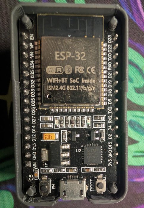
The ESP32-WROOM-32 is the module on the classic 38-pin "ESP32 DevKit"
board — a dual-core Wi-Fi + Bluetooth MCU with a PCB antenna, 4 MB of
flash, and a metal can, all for a couple of dollars. It's the same part behind
the other ESP32 builds on this site (the Bluetooth proxy, and the ESP32
Meshtastic boards in the node-build guide), so this is the short version
of "you just got one, now what."

One honest note up front: Espressif marks the plain WROOM-32 Not Recommended
for New Designs — the pin-compatible -32E / -32UE supersede it. But it's
everywhere, cheap, and almost certainly the DevKit already in your drawer, and
everything below applies to the whole WROOM-32 family.
[ Specs ]
Straight from the datasheet (v3.6):

  MCU        Xtensa dual-core 32-bit LX6, up to 240 MHz
  Memory     520 KB SRAM · 448 KB ROM · 8 KB RTC SRAM
  Flash      4 MB SPI flash (on-module) · 40 MHz crystal
  Wi-Fi      802.11 b/g/n, 2.4 GHz, up to 150 Mbps
  Bluetooth  v4.2 BR/EDR + Bluetooth LE
  GPIO       up to 32 (5 are strapping pins) — ADC, DAC, touch,
             UART, SPI, I2C, I2S, PWM, pulse counter, SD, TWAI/CAN
  Antenna    on-board PCB antenna (WROOM-32) / u.FL (-32U)
  Power      3.0–3.6 V · −40 to +85 °C
[ Power it ]
Three ways in, but the module itself only ever wants 3.3 V:

  — USB — the easy one. The micro-USB feeds 5 V into the board's
    on-board regulator, which makes the 3.3 V the module runs on. This also
    carries your serial console. Just plug it in.
  — VIN / 5V pin — 5 V from an external supply, through the same
    on-board regulator. Same as USB, minus the data line.
  — 3V3 pin — feed a clean regulated 3.3 V here to bypass the
    regulator. Efficient for battery builds, but there's no protection now, so
    don't exceed 3.6 V.

Never put 5 V on the 3V3 pin or on any GPIO — the ESP32 is a 3.3 V
part and is not 5 V tolerant.
[ Flash it ]
DevKits carry a USB-UART bridge (CP2102 or CH340), so flashing is just USB.

  1. Plug in. Install the CP2102 or CH340 driver if the port doesn't
     enumerate (Windows mostly auto-installs; Linux/macOS usually just work).
  2. Pick a toolchain:
       — Arduino IDE — add the ESP32 boards URL in Preferences, install
         "esp32" from Boards Manager, pick ESP32 Dev Module.
       — PlatformIO — board esp32dev, framework arduino or espidf.
       — ESP-IDF — Espressif's native C SDK (idf.py).
       — ESPHome — YAML, no C at all (what the BT proxy uses).
  3. Hit upload. All of them drive esptool underneath.

Boot mode: most DevKits auto-reset into the bootloader (the USB-UART
toggles EN/GPIO0 for you). If a flash ever fails to start, do it by hand: hold
BOOT, tap EN, release BOOT — that drops it into download mode.
[ GPIO cautions ]
The ESP32 has plenty of pins, but a few have strings attached. Learn these four
before you wire anything up:

  — 3.3 V logic only. Not 5 V tolerant — level-shift 5 V sensors.
  — GPIO34–39 are input-only. No output, no internal pull-up/down.
  — Avoid GPIO6–11. They're wired to the on-module SPI flash; using
    them crashes the chip.
  — Strapping pins (0, 2, 5, 12, 15) set boot behaviour. GPIO0 low =
    download mode; GPIO12 picks flash voltage (hold it low at boot). Fine as
    I/O once running, but don't hang anything on them that fights the boot
    state.

One more: ADC2 can't be read while Wi-Fi is on — use the ADC1 pins
(GPIO32–39) for analog if you're on the network.
[ First sketches ]
Onboard LED is usually GPIO2. Minimal Arduino sketch to prove the
toolchain end-to-end:

  void setup() { pinMode(2, OUTPUT); }
  void loop() {
    digitalWrite(2, HIGH); delay(500);
    digitalWrite(2, LOW);  delay(500);
  }

Upload, watch it blink, and you know your board, driver, and toolchain all
talk.
Then prove the radio — the whole reason you reached for an ESP32. This
scans nearby Wi-Fi and prints it to the serial monitor:

  #include <WiFi.h>
  void setup() {
    Serial.begin(115200);
    WiFi.mode(WIFI_STA); WiFi.disconnect();
  }
  void loop() {
    int n = WiFi.scanNetworks();
    Serial.printf("%d networks\n", n);
    for (int i = 0; i < n; i++)
      Serial.printf("  %-22s ch%2d %4ddBm %s\n",
        WiFi.SSID(i).c_str(), WiFi.channel(i), WiFi.RSSI(i),
        WiFi.encryptionType(i) == WIFI_AUTH_OPEN ? "open" : "enc");
    delay(5000);
  }

Open the serial monitor at 115200 baud and you've got a pocket Wi-Fi scanner
— the seed of half the ideas below.
[ Where to take it ]
The radios are the point — here's where an ESP32 pays its way on the kind
of thing this site is about:

  — Wi-Fi recon logger — grow the scan above into a wardriver:
    log SSID / BSSID / channel / RSSI (add a GPS module for coordinates).
    Passive and receive-only — a clean intro to 802.11 airspace.
  — BLE scanner / presence — enumerate nearby BLE advertisers,
    watch for specific MACs, and flip a home / away flag on presence.
  — Home Assistant sensor node — flash ESPHome and it becomes a
    temp / humidity / motion / door sensor feeding HA over Wi-Fi, no code.
  — Bluetooth proxy — relay BLE for Home Assistant so your sensors
    reach across the house (full build here).
  — LoRa mesh node — bolt on an SX127x radio and it can join a
    Meshtastic mesh — the job the built-in-LoRa Heltec boards do.
  — Deauth / anomaly monitor — watch management frames and alert
    on deauth floods or rogue APs. Defensive, and a solid Wi-Fi primer.
  — Lab rogue-AP / captive portal — stand up a test AP + portal for
    your own pentest lab or a CTF — authorized targets only.
  — CAN bus / OBD-II reader — the ESP32 has TWAI (CAN 2.0) built in;
    add a transceiver (SN65HVD230) and it reads and logs your vehicle's bus.
    Ties straight into the car-hacking gear here.
  — IR / 433 MHz capture-replay — an IR receiver + LED, or a cheap
    433 MHz RX/TX pair, turns it into a record-and-replay remote for your own
    devices (TVs, fans, garage, cheap RF plugs).

Most are a sketch and a cheap add-on module away — the board brings the
compute, the radios, and the glue.
[ Print a case ]
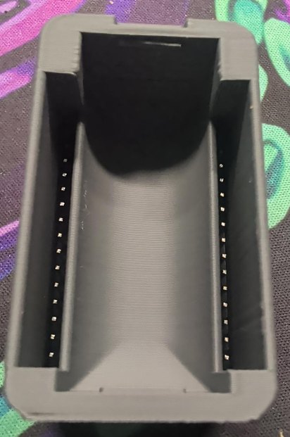
A simple three-part printed enclosure for the 38-pin DevKit — body shell, a
top lid, and a bottom lid with keyhole slots so it hangs on a wall. This is the
with-headers variant: the two channels down the long walls capture a board
that has its pin headers soldered on.
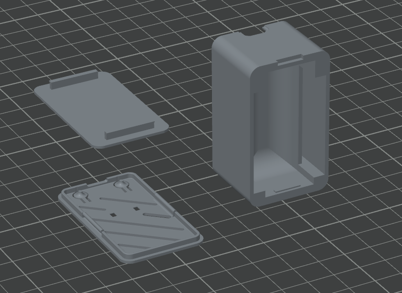
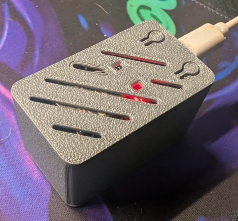
Print in PLA for the bench, PETG if it lives somewhere warm. Supports depend on
orientation — OrcaSlicer's auto-arrange orientation does need them, so set
the orientation yourself to keep the overhangs off the bed and you can skip
them. Three STLs (body, top lid, bottom lid) in one zip: