
[ Heltec WiFi LoRa 32 V4 Case Generator ]
[ Overview |
Get the files |
What you need |
Render targets |
Verify first |
Parameters |
OLED window |
Snap vs screw |
Assembly |
Materials ]
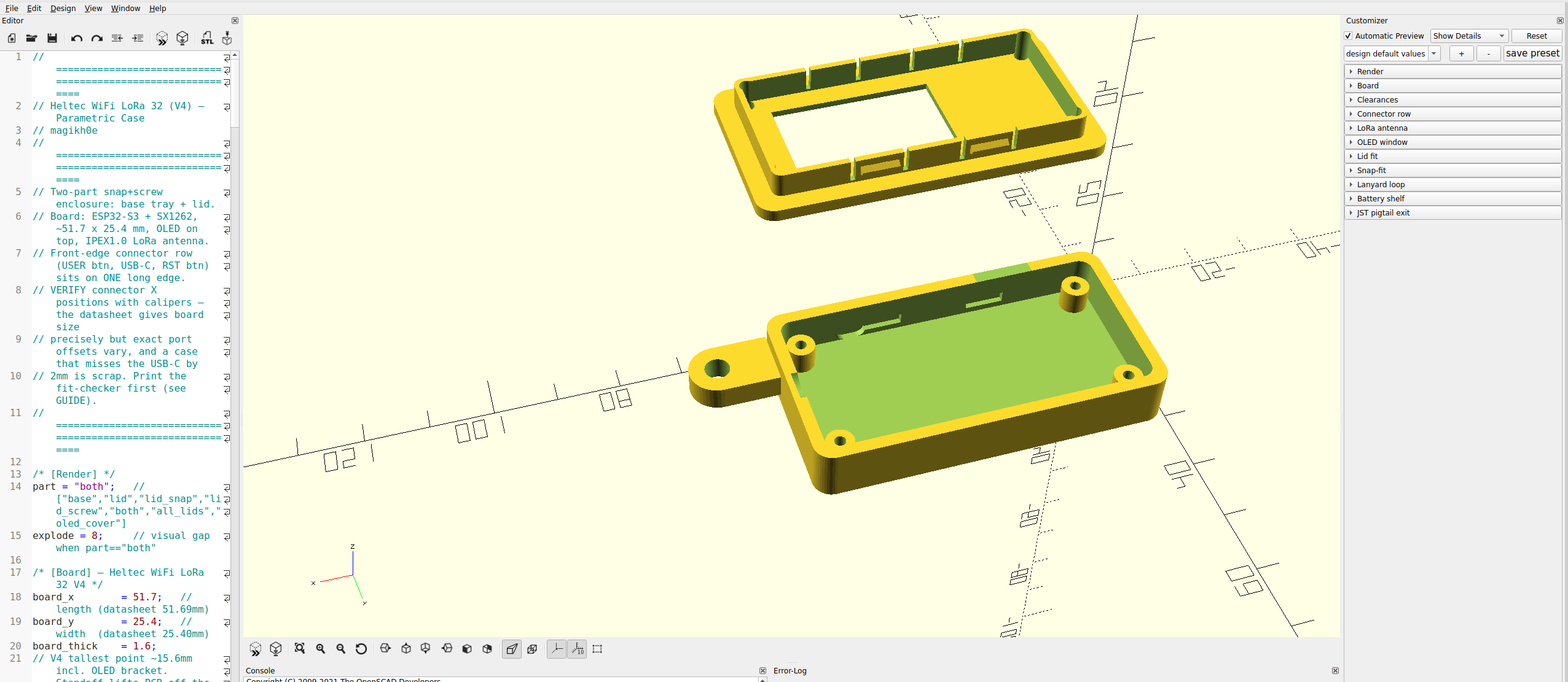
[ Overview ]
A parametric OpenSCAD enclosure for the Heltec WiFi LoRa 32 V4
— ESP32-S3 + SX1262, with a 0.96" OLED on top. It's the same two-part
snap+screw design as the WisBlock case, re-laid out for the V4's smaller
board and its row of connectors along one long edge.

Like the WisBlock generator, every dimension is tunable from variables at the
top of one .scad file. The V4-specific parts: a connector row (USER / USB-C /
RST) on a long edge, an optional OLED window in the lid, an SMA antenna hole,
and M2 mounting. Verify the connector positions before a long print — that's
the one dimension that varies, and the easy way to make scrap.
[ Get the files ]
  — Heltecv4_Case_Generator.scad — the generator. Open it
    in OpenSCAD and tune it to your board.
  — Print-ready STLs — built from the defaults, ready to slice:
    base, lid (snap), lid (screw), both lids, and the
    clear OLED cover.
  — GUIDE.md — this same guide as a text file, to keep with the model.

The STLs match the default variables; if you change board-specific dimensions,
re-export from the .scad so the parts stay in sync. It's a single self-contained
file, no libraries or dependencies. The model is also on GitHub
and Cults3D.
[ What you need ]
  — OpenSCAD (free) — the modeller that renders the .scad file.
  — Heltecv4_Case_Generator.scad — the generator itself.
  — A slicer — PrusaSlicer, OrcaSlicer, Cura, Bambu Studio, any.
  — Calipers — matter more here than on the WisBlock, since the
    connector X positions are the make-or-break dimension.

Press F5 for a fast preview, F6 for a full render. The Customizer
(Window menu) exposes the variables as labelled sliders and toggles, grouped
under [Board], [Connector row], [OLED window], and so on. Export with
File → Export → Export as STL.
[ Render targets ]
The part variable picks what you get:

  — base — the tray only.
  — lid — a lid following your snap / screw toggles.
  — lid_snap / lid_screw — snaps only, or screw holes only.
  — all_lids — both lid versions side by side on one plate.
  — oled_cover — the clear window cover (print in transparent filament).
  — both — base + lid exploded, for on-screen preview only.

both floats the lid above the base for inspection, so export the base and a
lid separately to print. The base is shared — it carries both the snap
recesses and the screw posts, so either lid drops onto the same tray.
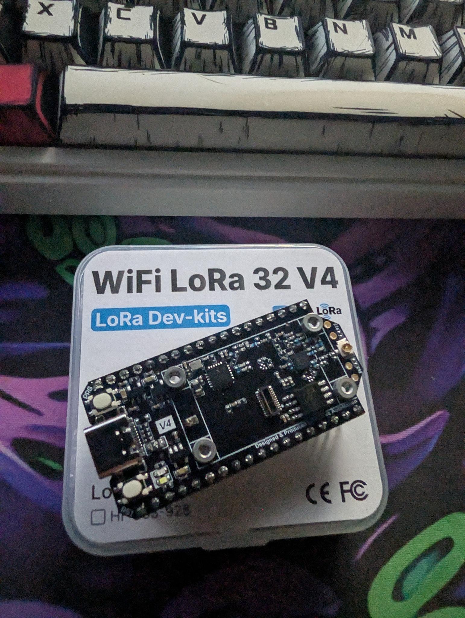
[ Verify first ]
This is the make-or-break step for the V4. The board size is exact, but the
X positions of the USB-C and buttons along the front edge have to match your
board, or the ports miss their holes. Measure from the left end of the PCB to
the center of each feature and set:

  — usbc_x (14) — USB-C center.
  — usrbtn_x (6) — USER button center (0 disables it).
  — rstbtn_x (22) — RST button center (0 disables it).
  — front_edge (y0) — which long edge the row faces; flip to y1
    if your board sits the other way round.

Fit-checker trick: set comp_clear = 1 and print just the base. You get
a shallow tray that confirms the footprint, USB-C, and button alignment in
about 15 minutes of filament. Adjust the X values, reprint if needed, then set
comp_clear back to 12 for the real thing.
[ Parameters ]
The settings you'll actually reach for, beyond the connector row above:

  — clr (0.4) — gap around the PCB. Tight to seat? 0.5. Loose? 0.3.
  — comp_clear (12) — headroom above the board; the OLED bracket is
    the tall part, so raise it if you stack anything on top.
  — ant_mode (sma) — sma cuts a bulkhead hole for a u.FL-to-SMA
    pigtail (best range); internal leaves no hole, antenna stays inside.
  — use_snaps / use_screws — the lid strategy (next section).
  — snap_depth (0.9) — click strength. 0.6 opens easy, 1.2 locks hard.

The full table — every board, clearance, antenna, and snap variable — is in
the GUIDE that ships with the model.
[ OLED window ]
The V4's 0.96" screen sits on top, so the lid has an optional window:

  — oled_window (true) — cut the window, or set false for a solid
    lid on a headless node.
  — oled_recess (true) — sink a ledge around the window so a clear
    cover sits flush instead of proud.
  — oled_w / oled_h / oled_cx / oled_cy — the window size and where
    it sits on the board; verify these against your screen.

For the cover you have three options: print part = "oled_cover" in clear
PETG or PLA, drop in the bundled heltec_v4_oled_cover.stl, or cut a 1 mm
acrylic rectangle to size. Or just leave the window open.
[ Snap vs screw ]
The base takes either lid, so it's a per-print choice:

  — Snaps — cantilever catches click shut. Fast to open, no
    hardware — good for a node you reflash often.
  — Screws — four M2 self-tappers into the corner posts. Clamps
    tight; better for outdoor or a gasketed weather build.
  — Both — snaps align it, screws clamp it.

Opening it a lot? Melt M2 heat-set inserts into the posts and run machine
screws — far more durable than repeatedly self-tapping plastic.
[ Assembly ]
  — Seat the board — the V4 drops onto the four M2 standoff posts.
  — Antenna — SMA build: mount the u.FL-to-SMA pigtail through the
    bulkhead hole, tighten the nut, then clip the u.FL onto the board's IPEX1.0
    connector. Internal build: just leave the IPEX antenna inside.
  — Battery — route the SH1.25 lead out through the pigtail slot.
  — OLED cover — optional; drop the clear cover into the recess, a
    dab of clear glue holds it.
  — Close it — snap shut, then drive four M2 x 6 to 8 mm screws into
    the posts.
[ Materials ]
  — PLA — easiest to print, but softens in heat and sun, so the
    snaps relax over time. Indoor / bench only.
  — PETG — the all-round pick here: heat-tolerant, flexes well for
    repeated snap cycles, decent UV resistance.
  — ASA — best for sustained outdoor sun.

For a sealed outdoor node, use the screw lid (optionally with a gasket) in PETG
or ASA. Port offsets and tolerances vary by board and printer, so always run
the connector-row fit-checker before a long print.