
[ WisBlock Case Generator ]
[ Overview |
Get the files |
What you need |
Render targets |
Print workflow |
Verify first |
Parameters |
Snap vs screw |
Assembly |
Materials ]
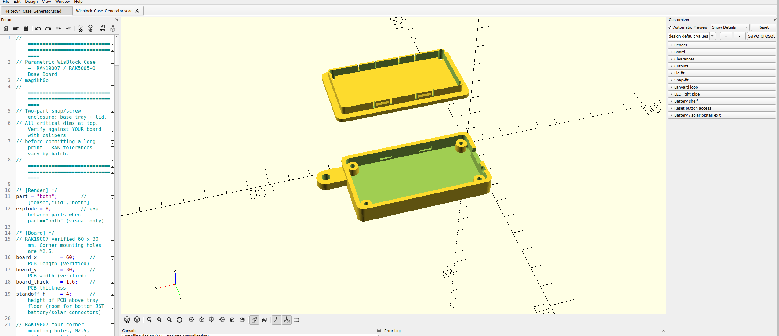
[ Overview ]
A parametric OpenSCAD enclosure for the RAK19007 WisBlock base board
+ RAK4631 core — the Meshtastic starter kit. One .scad file produces a
base tray and a choice of lids, every dimension tunable from variables at the
top. No CAD skills needed: change a few numbers, render, export an STL.

The defaults are built from the RAK19007 datasheet and verified for manifold
geometry. Tolerances drift by board batch and by printer, so test-fit before
you commit to a long print — there's a one-minute fit-checker trick below.
[ Get the files ]
  — Wisblock_Case_Generator.scad — the generator. Open it
    in OpenSCAD and tune it to your board.
  — Print-ready STLs — built from the defaults, ready to slice:
    base, lid (snap), lid (screw), and both lids.
  — GUIDE.md — this same guide as a text file, to keep with the model.

The STLs match the default variables; if you change board-specific dimensions,
re-export from the .scad so the parts stay in sync. It's a single self-contained
file, no libraries or dependencies. The model is also on GitHub and Cults3D.
[ What you need ]
  — OpenSCAD (free) — the modeller that renders the .scad file.
  — Wisblock_Case_Generator.scad — the generator itself.
  — A slicer — PrusaSlicer, OrcaSlicer, Cura, Bambu Studio, any.
  — Calipers (optional, recommended) — to verify a couple of
    board dimensions before a long print.

Open the file, press F5 for a fast preview or F6 for a full render. Turn
on the Customizer (Window menu) and the variables show up as labelled sliders
and toggles, grouped under headings like [Board] and [Lid fit] — no code
editing required. Export the rendered part with File → Export → Export as STL.
[ Render targets ]
The first variable, part, picks what you get:

  — base — the tray only.
  — lid — a lid following your snap / screw toggles.
  — lid_snap — snaps only, no screw holes.
  — lid_screw — screw holes only, no snaps.
  — all_lids — both lid versions side by side on one plate.
  — both — base + lid exploded, for on-screen preview only.

Two gotchas. both is for looking, not printing — it floats the lid above
the base, so export the base and a lid separately to print. And the Customizer
dropdown only lists base / lid / both; the other three are valid render targets,
you just type them into the part variable by hand. The base is shared — it
always carries both the snap recesses and the screw posts, so either lid drops
onto the same tray. Print one base, then whichever lid(s) you want.
[ Print workflow ]
  — Base — set part = base, render (F6), export. Prints flat, open
    side up, no supports.
  — Lid — set part = lid_snap (or lid_screw), render, export.
    Prints lip-up; the chamfered snaps stay under ~45° so no supports are
    needed on most printers.
  — Assemble — seat the board, route the antennas, close the lid
    (full steps below).
[ Verify first ]
The defaults match the datasheet, but three things reward a caliper check for a
tight fit:

  — Mounting-hole inset — hole_inset_x / _y (2.5 mm). Measure if
    you want the four posts to line up perfectly.
  — USB-C cutout — usbc_w / usbc_h (9.5 / 3.6). A chunky cable
    overmold wants another 1 to 2 mm.
  — Reset / pigtail side — both sit on the USB-C short end. If
    your board's reset is mirrored, flip the sign on reset_offset and
    pigtail_offset.

Fit-checker trick: set comp_clear = 1 for a throwaway shallow tray that
confirms the footprint and the cutouts without burning filament on full-height
walls. Set it back to 14 afterward. A few minutes here saves hours of failed
long prints.
[ Parameters ]
Everything lives in labelled groups at the top of the file; the full table is in
the README that ships with the model. The ones you'll actually reach for:

  — clr (0.4) — gap around the PCB. Tight to seat? 0.5. Loose? 0.3.
  — comp_clear (14) — headroom above the board; raise it for a
    taller stack or a bulkier antenna.
  — use_snaps / use_screws — the lid strategy (next section).
  — snap_depth (0.9) — click strength. 0.6 opens easy, 1.2 locks hard.
  — ant_d (0) — SMA bulkhead hole. 0 is correct for the stock IPEX
    antenna kit; set ~6.5 only if you switch to an SMA pigtail.
  — battery / lanyard / ledpipe — optional extras, off or on by a
    single toggle each.
[ Snap vs screw ]
The base takes either lid, so this is a per-print choice, not a permanent one:

  — Snaps — cantilever catches click shut. Fast to open, no
    hardware — great for a bench node you reflash often.
  — Screws — four M2.5 self-tappers into the corner posts. Clamps
    tight; better for outdoor or a gasketed weather build.
  — Both — snaps align it, screws clamp it. Belt and suspenders.

For a node you open a lot, melt M2.5 heat-set inserts into the posts and run
machine screws — far more durable than repeatedly self-tapping plastic.
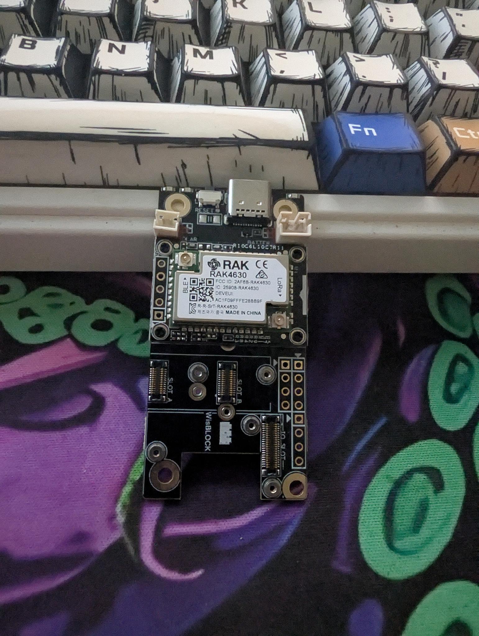
[ Assembly ]
  — Seat the board — the RAK19007 drops onto the four standoff posts.
  — Route the antennas — the RAK4631 kit ships two adhesive IPEX/u.FL
    flat flags (LoRa + BLE). Peel and stick them to the inside of the lid or a
    side wall, kept apart and against non-metal for range. No drilled SMA hole.
  — Battery — route the JST lead out through the pigtail slot.
  — Close it — snaps just click; screws drive M2.5 x 6 to 8 mm into
    the posts; both means click for alignment, then clamp.
[ Materials ]
  — PLA — easiest to print, but softens in heat. A hot car or direct
    sun relaxes the snap click and can sag the case. Indoor / bench only.
  — PETG — the sweet spot: heat-tolerant, flexes well for repeated
    snap cycles, decent UV resistance.
  — ASA — best for sustained sun and outdoor exposure.

Living outside? The screw lid, optionally with a gasket, holds up far better than
snaps alone. Dimensions come from the published datasheet and are verified for
manifold geometry, but tolerances vary by batch and by printer — always
test-fit before a long or multi-color print.