
[ The Making of SYN/ACK ]
[ Overview |
Two boards |
The table |
Physics |
Drawing fast |
Sound |
Testing |
Real buttons |
The cabinet |
What it taught |
Get it ]
[ Overview ]
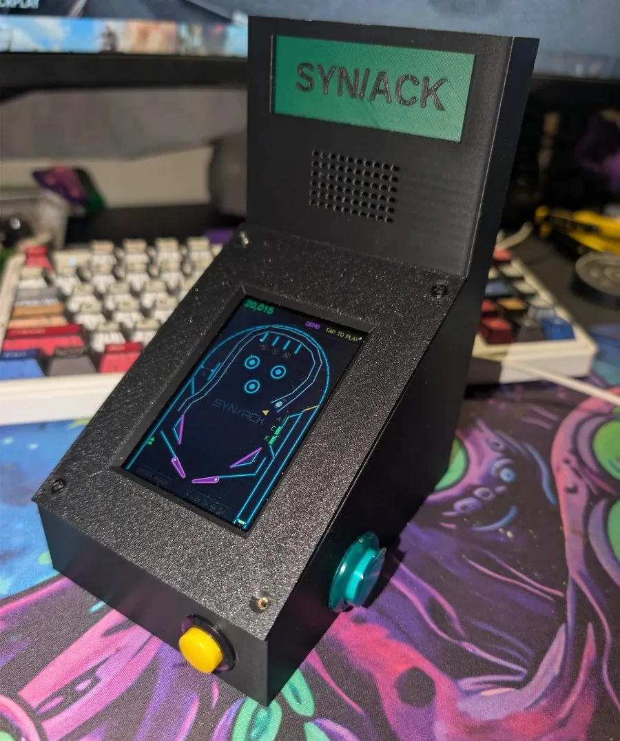
SYN/ACK is a pinball table for 3.5-inch ESP32 touch boards: a 320 × 480
neon playfield where the lanes spell SYN, the targets spell ACK, and
completing the handshake floods the table with balls. It started on a Sunton
“CYD”, moved to an ESP32-S3 board, and ended up in a printed tabletop cabinet
with real arcade buttons and a backbox.

This is the story of how it got there, and the problems worth remembering
along the way. The source, the PC tests and the printable cabinet are all on
GitHub: magikh0e/synack-pinball.
[ Two boards, one table ]
           Sunton ESP32-3248S035R (“CYD”)    LCDwiki ES3C35P
  Chip     ESP32                             ESP32-S3, with PSRAM
  Display  ST7796, SPI                       ST77922, quad SPI
  Touch    XPT2046, resistive, one point     capacitive, multi-touch
  Sound    a buzzer on a PWM pin             ES8311 codec and amplifier
  Lights   an RGB LED                        an RGBW NeoPixel

Both are 320 × 480 portrait, so the table itself never had to change.
Everything that does differ lives behind one small interface:
game.hpp is plain C++ with no Arduino in it, which turned out to be the
most important decision in the project: the same physics and rules compile
into a test program on a PC, where a bot can play hundreds of balls in
seconds.
[ The table ]
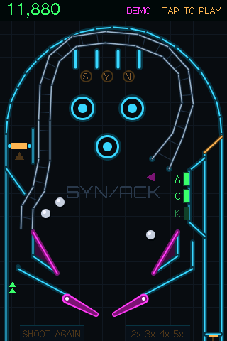
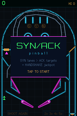
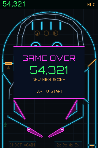
The theme is the TCP handshake:

  — Lighting all three SYN lanes at the top raises the multiplier (up
    to 5×) and arms SYN.
  — Knocking down all three ACK targets on the right scores 5,000, or a
    25,000 HANDSHAKE if SYN is armed, and relights the kickback.
  — A HANDSHAKE starts SYN FLOOD: two more balls are plunged in and
    everything scores double. The second HANDSHAKE in a game also earns an
    extra ball.
  — The UPLINK ramp climbs the right side, crosses over the top and
    drops the ball into the left inlane. It lights the next SYN lane, and
    during multiball it’s a 15,000 jackpot.
  — A spinner in the left orbit pays double while SYN is armed.
  — A skill shot zone on the plunger’s power meter, a kickback in the
    left outlane, a ball save, and an end-of-ball bonus count-up.

When nobody is playing, a bot plays a silent demo game with a light show,
and it never sets the high score.
[ Physics: small steps and capsules ]
The ball moves in fixed steps of 1/600 of a second, however fast the screen
draws. Every wall, post, sling, target and flipper is either a circle or a
capsule (a line segment with a radius), so a single closest-point
routine handles every collision. Flippers carry their surface speed into the
bounce, which is what makes a flick feel like a flick.

Tuning was done by measurement more than by feel. The first players found
the flippers weak (their up speed went from 24 to 29 rad/s) and the outlanes
greedy. Narrowing the outlane gap did nothing, because it was already barely
wider than the ball; shortening the separator above it did. In a 600-ball
bot run, outlane drains fell from about 75% to 53%.

The ramp’s exit is a good example of how small changes matter: angled
slightly left, it fed balls straight into the left outlane, and the average
ball life fell from 32 to 22 seconds. Pointed straight down, it feeds the
flipper.

The ball that slowed down. The most stubborn bug was a ball that
sometimes crawled down to the flippers. It had three separate causes:

  1. The ramp crawled. A weak shot could take 3.5 seconds to come back
     down. The ramp now keeps a minimum speed past its crest.
  2. Slow motion. When too many parts of the screen changed at once,
     the game fell back to redrawing everything, about 170 ms on the S3.
     The physics caps each frame’s time step at 50 ms, so those frames
     played in slow motion. Now the extra changes are merged into the
     nearest existing rectangle.
  3. Rolling friction. Each collision took a little speed off along the
     surface. But a ball rolling along a guide touches it on every step,
     600 times a second, so rolling was capped at about 50 px/s:
// a touch of friction on real impacts only. A ball rolling along a
// guide or flipper "hits" it every substep as gravity presses it in, and
// braking each of those (600/s) capped rolling at ~50 px/s
if (vn < -60) {
  V tg = perp(n);
  rel = rel - tg * (dot(rel, tg) * 0.015f);
}
The roll down the inlane went from 2.6 seconds to 1.0, and a test now
measures it.
[ Drawing fast ]
Redrawing the whole 320 × 480 screen every frame is far too slow over SPI,
so the game tracks dirty rectangles: the ball’s old and new position, a
lamp that changed, the score. Each frame merges the overlapping ones and
redraws only those, through two 320 × 48 DMA buffers so one is drawn while
the other is sent. That runs at around 89 frames a second on the CYD.

When the whole screen does need redrawing, it’s spread over ten frames,
48 rows at a time, instead of stalling one frame for 170 ms. The worst frame
dropped to about 32 ms on the S3 and 35 ms on the CYD.

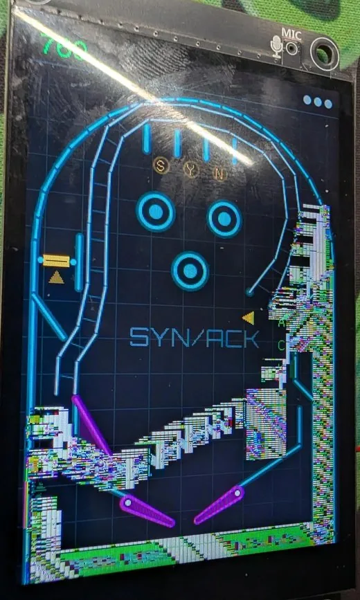
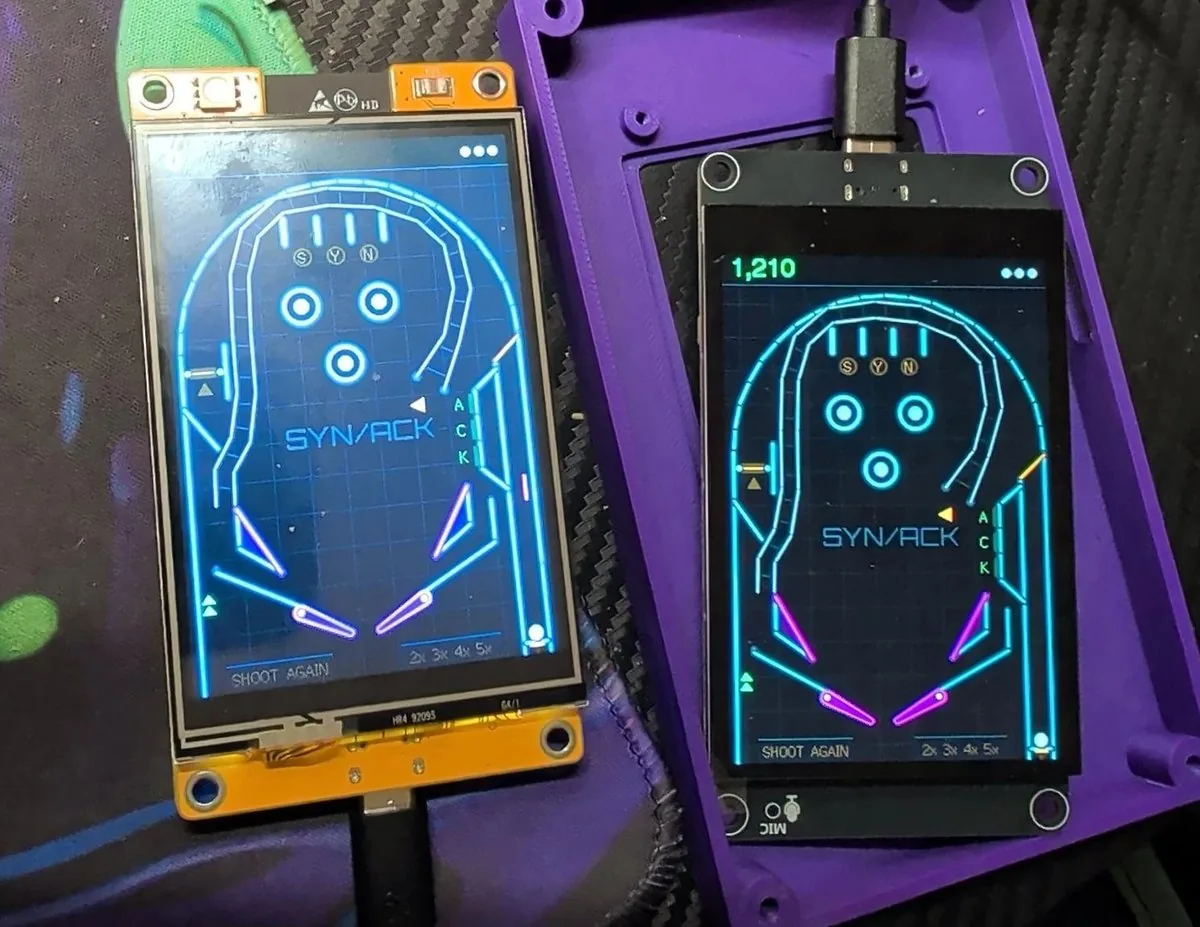
The diagonal smear. The ES3C35P’s first images came out sheared
diagonally. The cause was in the ST77922’s datasheet: the start column and
the width of a drawing window must both be multiples of 4. Anything else
is quietly misdrawn: each row lands a few pixels off from the one before, so
every update smears into a diagonal staircase, worst wherever the ball has
been.
The fix is to widen every rectangle to the next 4-pixel boundary before
drawing:
const int A = board::ALIGN_X;  // 4 on the ES3C35P, 1 on the CYD
for (int i = 0; i < n; i++) {
  int x0 = d[i].x / A * A;
  int x1 = min((d[i].x + d[i].w + A - 1) / A * A, (int)pb::SCR_W);
  d[i].x = x0;
  d[i].w = x1 - x0;
}
The board’s own screenshot command couldn’t show this bug, since it reads a
copy of the image in memory rather than the panel. Only a photo of the real
screen did.
[ Sound ]
The CYD has a buzzer, so it plays one square-wave note at a time. The
ES3C35P has a real audio codec, so it gets a small synthesizer: three voices
mixed together, each a square, pulse, triangle, saw or noise wave that can
sweep in pitch and decay like a struck sound.

Bumpers thump, the spinner ticks, the flippers make a short noise burst when
they hit the ball, and multiball gets an arpeggio fanfare. On the CYD the
same events play the first note of each sound.
[ Testing without the hardware ]
host/sim.cpp builds the game for a PC (inside a Docker container
with g++). It:

  — draws the table to image files,
  — sweeps plunger strengths and flipper shots,
  — lets the demo bot play 300 balls, failing if a ball escapes the table
    or a feature (multiball, the ramp, the lanes) never triggers,
  — checks the rules one by one: multiball, the bonus count, the skill
    shot, the extra ball, and that the demo never sets the high score,
  — and checks that redrawing only the dirty rectangles gives exactly the
    same pixels as a full redraw.

The long bot run found two places where the ball could get trapped (where
the inlane guide meets the flipper pivot, and under the slingshots) before
any person did. On GitHub, every push builds the firmware for all three
targets and runs the tests.

One detour worth mentioning: the ESP32’s compiler crashed outright with an
internal error once the bonus code was inlined into the main game loop.
Marking those helpers “don’t inline” was the fix.
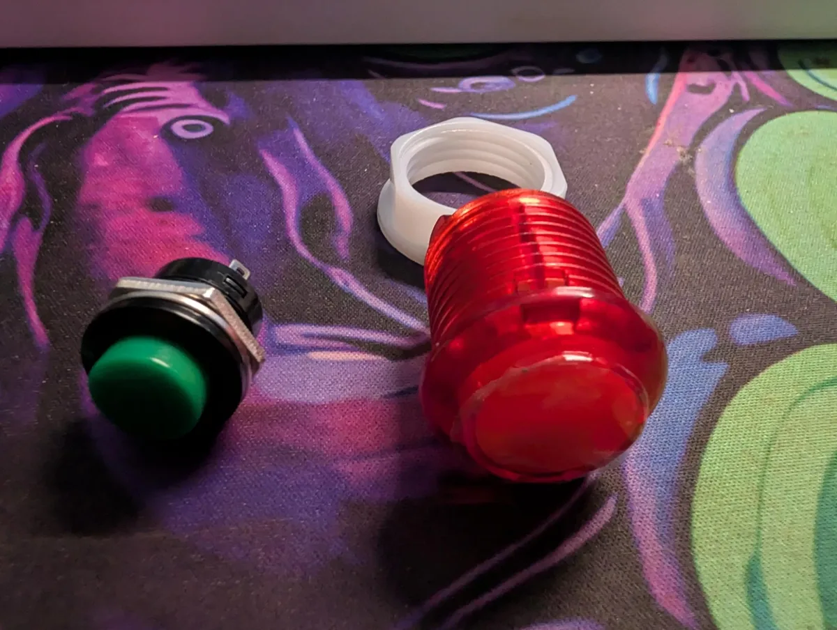
The buttons. Two 24 mm arcade buttons work the flippers, and a 16 mm
momentary panel button on the front is the launcher (the case can also take
a third 24 mm button there).

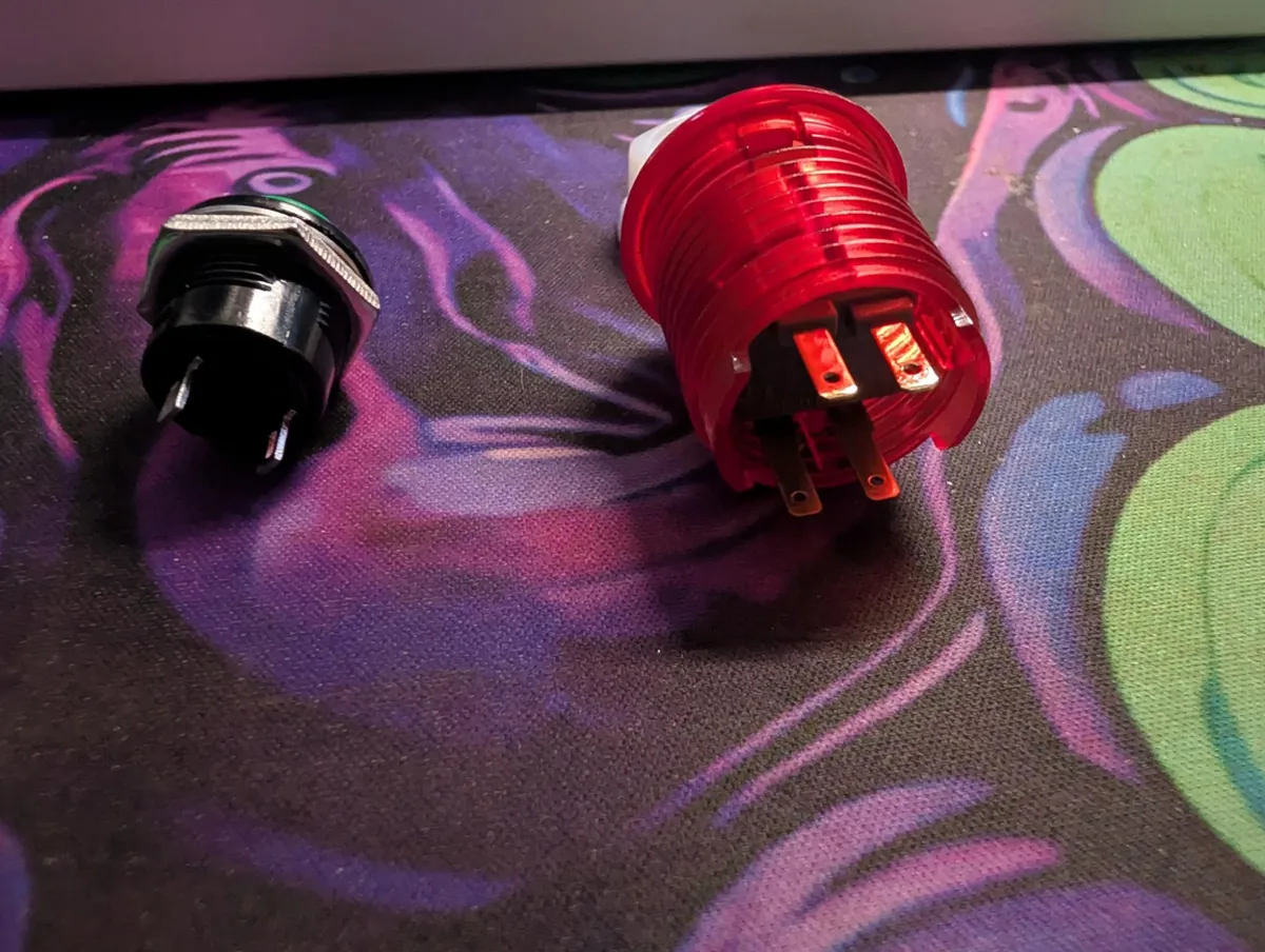
A plain arcade button has two tabs: just the switch. A lit one has four: two
power its LED and two are the switch. These flipper buttons are the lit
kind, with LEDs the game lights, so they get four wires each. The tabs are
all the same size, 2.8 mm wide, a standard size for push-on spade
connectors: 2.8 mm female spade terminals fit them, so the button end
needs no soldering either. The 16 mm launch button’s two tabs look about
the same size, so the same terminals should fit there too.

Spade terminal kits sort them by tab size: get the 2.8 type (for 22–16
AWG wire); the 4.8 and 6.3 types are for bigger tabs. Slide a clear sleeve
over each crimp, since the four tabs sit close together.

The MX1.25 kit’s leads are thin, about 26–28 AWG, below the 22 AWG those
terminals are made for, so a plain crimp may not grip. Strip a longer end,
fold it back on itself to double it, crimp over that, and give it a tug.

Get 5 V lit buttons. They’re sold in 5 V and 12 V versions, and the
lamps here run off the board’s own 5 V (the serial socket’s pin 1). A 12 V
button’s LED would barely light on that, if at all.

The 24 mm lit button, from its drawing:

  thread   24 mm across
  bezel    27.6 mm across
  cap      19.6 mm across
  body     33.2 mm long
  tabs     2.8 mm wide, all four
On the CYD, the flipper buttons go on the IO22 and IO21 pins of its
extension socket, and on the ES3C35P on its serial socket (IO43 and IO44,
which are free because the S3 talks to the PC over its own USB). On both, a
launch button is wired across the board’s BOOT button: hold to charge the
plunger, release to fire.

Two things to watch:

  — The ES3C35P’s serial socket has 5 V on pin 1 (marked with a small
    triangle and printed 5V). Ground is pin 2. Read the labels printed
    on the board, not a guess from the schematic.
  — The flipper buttons in the cabinet have 5 V LEDs, lit by the game on
    IO45 and IO46. Those two pins decide how the chip starts up, so each
    lamp is switched by a transistor, which keeps the pin low while the
    board boots.
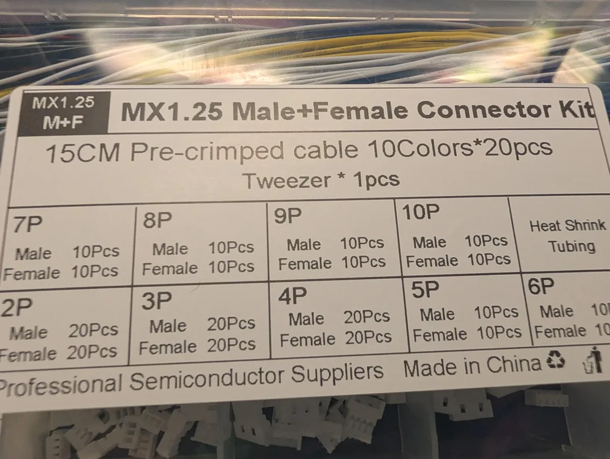
Plugs, not solder. The ES3C35P’s sockets are 1.25 mm pitch MX1.25:
the serial socket for the flipper buttons, the expansion socket for their
lamps, and the speaker socket. A kit of MX1.25 plugs with pre-crimped leads
covers all of them with no soldering at the board: 4-pin for the serial and
expansion sockets, 2-pin for the speaker.

Search for MX1.25 by name. “1.25 mm” or “JST 1.25” on its own also turns
up other connector families with the same pitch, JST GH among them. They
look alike and don’t mate, and it took two wrong kits before this one fit.
[ The cabinet ]
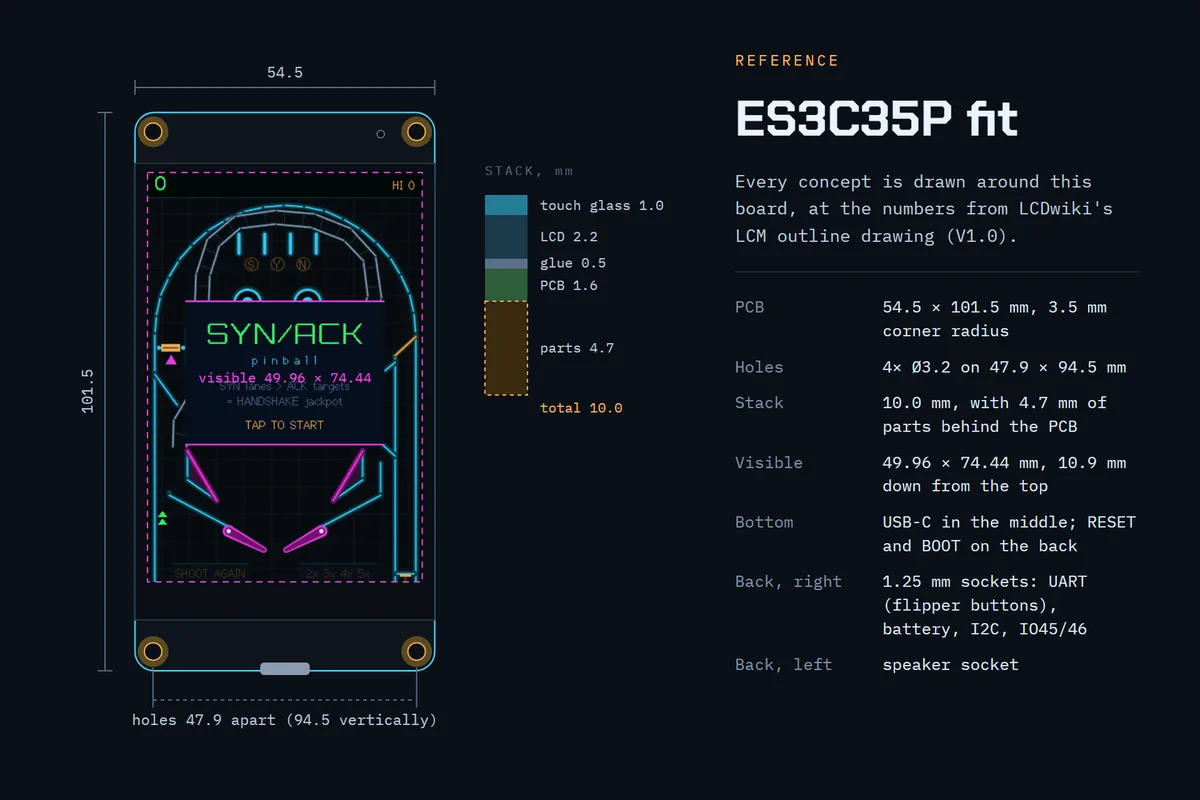
Concepts. Three ideas were drawn up around the board’s real dimensions:
a tabletop cabinet, a handheld, and a desk wedge, each checked against the
same fit reference for the ES3C35P.
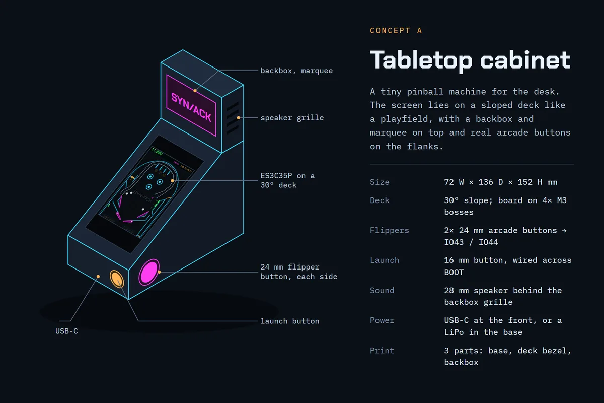
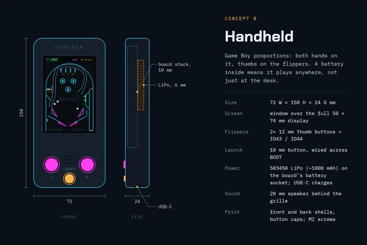
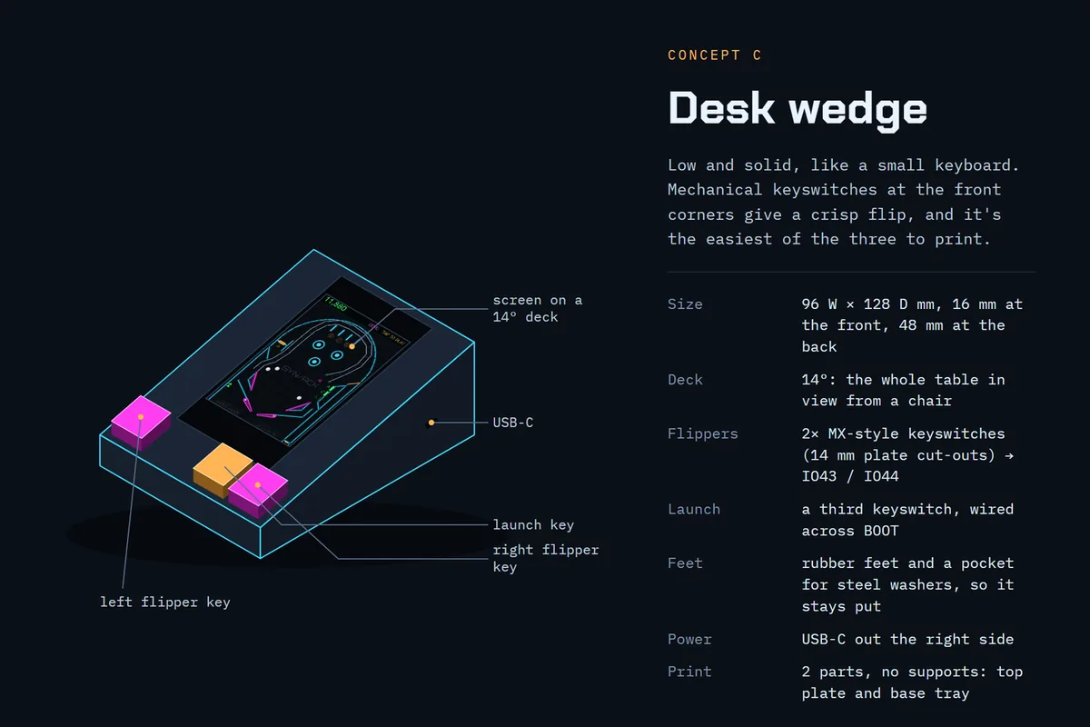
The tabletop cabinet won: it looks like a pinball machine, it has room for a
proper speaker, and the arcade buttons sit where real flipper buttons do.

From concept to model. The case is one OpenSCAD file
(case/cabinet.scad), driven by measurements: the board’s outline
drawing, the buttons’ datasheet, the speaker as measured. Changing a number
reshapes every part that depends on it.

The concept was 72 mm wide. The real 24 mm arcade buttons stick out about
41 mm behind the side wall once their connectors are on, and the two face
each other, so the cabinet grew to 92 mm. The model checks this itself:
rendering it prints the gap between the two buttons’ connectors, and fails
if any clearance goes negative.

A “clash” render checks the hardware against the printed parts: the USB plug
and socket, the speaker and the marquee card, both in place and along the
path each takes to get there. It has to come out empty.
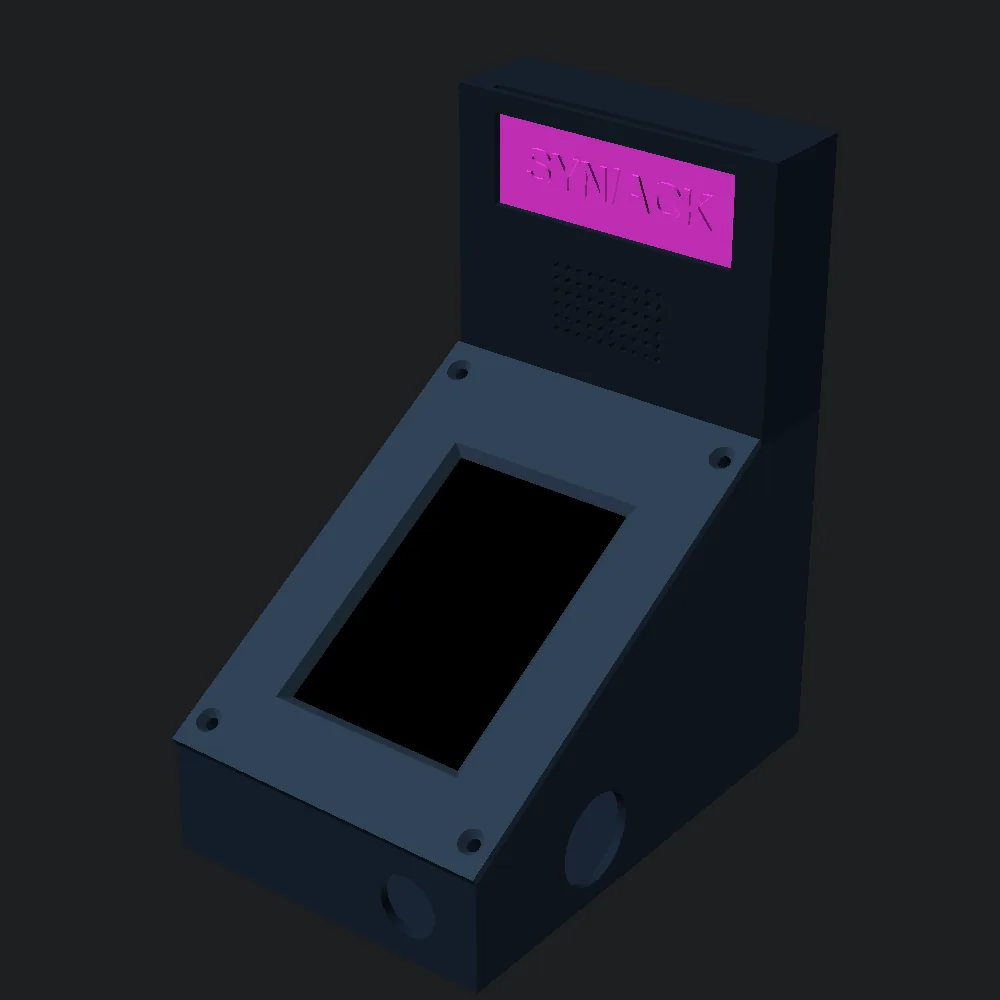
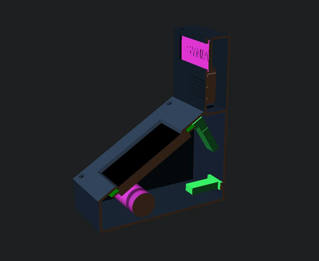
Turning the board upside down. The ES3C35P has its USB-C, RESET and BOOT
at one end. Mounted the obvious way, the USB would face the player. Mounted
upside down, it faces the back of the cabinet and its sockets land nearer
the buttons and the speaker. The es3c35p-cabinet build turns the picture
and the touch 180° to match. Since a rectangle turned half a turn is just
its pixels in reverse order at the mirrored position, that’s a few lines in
the board layer and nothing anywhere else.

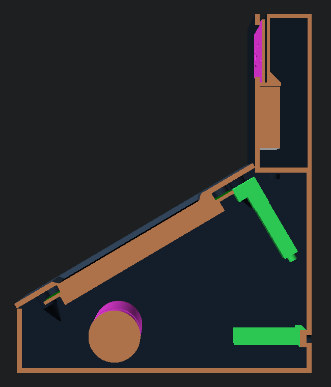
Getting the USB out the back. A panel-mount USB-C socket sits in the
back wall, with a short extension to the board. With a straight plug, the
cable had to double back hard inside the backbox. A small 90° adapter on
the board’s port turns the plug down toward the back wall instead, and the
cable then reaches the socket in one loose loop:
Printing it.

  — Four parts: body, deck, backbox and marquee card, none needing
    supports.
  — The backbox prints upside down. An open-bottomed box has a roof in
    every other orientation; this way every wall rises straight from the
    bed. The only bridge left is the top of the marquee window.
  — The speaker (40 × 28 × 9 mm) slides up into the backbox from
    below, against the grille, until it stops under a shelf.
  — The marquee card drops in through a slot in the top and stands on
    that shelf. Its letters are raised 0.8 mm, so the slot needs room for
    them: the first fit was too tight to print. Black letters on a black
    card vanished; printed in green with black letters, it reads from
    across the room.
[ What it taught ]
  — Keep the game portable. Being able to run the real physics on a PC
    paid for itself many times: tuning, soak tests, and catching traps no
    human had found.
  — Measure, then change one thing. The outlanes, the ramp exit and the
    slow ball were all settled by numbers from bot runs, not by feel.
  — Per-contact effects must ignore resting contact. Anything applied
    “on every collision” also runs 600 times a second on a ball that’s just
    rolling.
  — Read the datasheet’s fine print. The 4-pixel rule and the 5 V pin
    were both written down. They just weren’t where anyone looked first.
  — Check how parts go in, not only where they end up. A model can fit
    perfectly once assembled and still be impossible to assemble.
  — Photos beat screenshots for anything the panel itself gets wrong.
[ Get it ]
Everything is on GitHub at magikh0e/synack-pinball:

  — the firmware, a PlatformIO project with three builds: the CYD, the
    ES3C35P, and es3c35p-cabinet for the board mounted upside down,
  — host/, the PC tests (sh host/run.sh, needs Docker),
  — case/, the OpenSCAD cabinet, with STLs ready to print.

Build and flash with PlatformIO:

  pio run -t upload --upload-port COM4               CYD
  pio run -e es3c35p -t upload --upload-port COM6    ES3C35P (native USB)
  pio device monitor                                 fps, worst frame, heap
[ See Also ]
Hack the Planet Pinball # the browser pinball table on this site
Pueo # another CYD build: four radios on one board
Getting Started with ESP32 Development # PlatformIO, flashing and the serial monitor
Calibrating 3D Printer Filament # before you print the cabinet
Hardware Hacking (parent) # arduino, ESP32, firmware, RF
SYN/ACK on GitHub # source, PC tests and the printable cabinet