
[ Using a Basic Multimeter ]
[ Overview |
Dial & jacks |
Two safety rules |
Across vs. in series |
Voltage |
Continuity & resistance |
Battery test |
Current |
NCV, hold, light |
What goes wrong ]
[ Overview ]
A multimeter is the one tool the rest of this site keeps telling you to reach
for. Every “meter it,” every “check the voltage,” every “is this trace
connected” comes back to this box and two probes. If you can measure voltage,
check continuity, and read resistance, you can debug most of what goes wrong on
a bench.

The worked example is an AstroAI DM130B, a $15 auto-ranging pocket meter,
because it is exactly the kind most people own and the kind that intimidates
beginners with a dial full of symbols. Auto-ranging is the friendly part: you
pick what to measure (volts, ohms, amps), not the range, and the meter figures
out the rest. There is no “200 / 2000 / 20k” to guess at.

Nothing here is specific to that one meter. Any cheap DMM has the same handful
of positions and the same two rules, so the method carries to whatever is in
your drawer.
[ The dial and the jacks ]
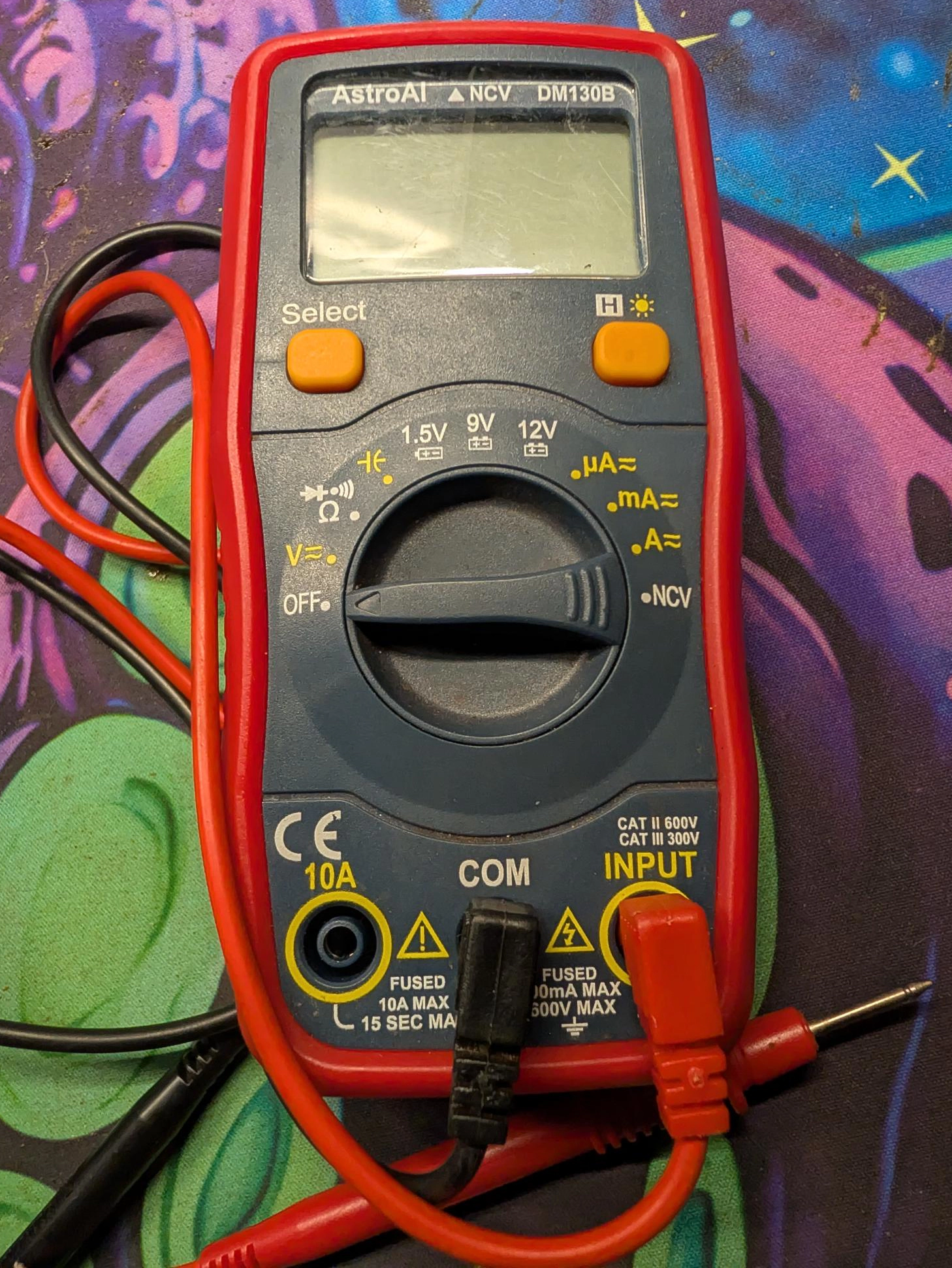
Two things to find before you measure anything: the dial position, and which
holes the leads go in.

The dial, clockwise from OFF, groups into five jobs:

  V                 voltage, AC and DC (the one you use most)
  Ω · ⓑ · diode   resistance, continuity beep, and diode test —
                    they share one position; Select cycles them
  1.5V 9V 12V       battery-test positions (voltage under a load)
  µA mA A          current — small to large (the dangerous one)
  NCV               non-contact AC voltage sniffer

The jacks, and this is the part that saves your fuse:

  COM     the black lead lives here, always. It is the reference (−).
  INPUT   the red lead, for voltage, resistance, continuity, and small
          current. Fused, 600V max. This is where red sits 95% of the time.
  10A     the red lead moves here only to measure large current, and
          only briefly (10A for 15 seconds, then it overheats).

Two buttons round it out: Select switches AC/DC and cycles the shared
functions, and H (with a sun icon) holds the reading on screen and turns on
the backlight.
[ The two rules that keep the meter alive ]
Everything else is detail. These two are the difference between a working meter
and a blown fuse (or a scare).

  1. Black never moves; red moves only for amps. Black stays in COM. Red
     stays in INPUT for volts, ohms and continuity. Red goes to the 10A jack
     only when you are deliberately measuring large current, and comes
     straight back afterward.
  2. Never put the probes across voltage while set to current. In a current
     mode the meter is almost a piece of wire. Touching it across a battery or
     outlet is a dead short through the meter. This is the single most common
     way beginners kill a DMM.

Rule 2 is really just “current is different.” The next section shows why.
[ Across vs. in series ]
Voltage, resistance and continuity are measured across a thing: you touch
the two probes to two points and the circuit stays whole. Current is measured
in series: you break the circuit open and let the current flow through the
meter. Getting these two topologies straight is 90% of using a meter correctly.
[ Measuring voltage ]
This is nine of every ten measurements. Black in COM, red in INPUT, dial to
V. Press Select if you need to flip between DC and AC; the display tells you
which mode it is in. Touch the probes across the two points you care about.

  — DC (batteries, packs, boards, wall-adapter output): red on the
    positive side, black on the negative. A leading minus sign just means the
    leads are the other way round — harmless, flip them or read the number.
  — AC (wall outlets, mains): polarity does not apply. Treat anything at
    mains voltage with respect; a $15 meter is fine here but you are not.

Because it auto-ranges, you never pick a scale — read the number and the unit
the display shows (mV vs V). Worked examples straight off this site:

  — a single 18650 cell reads 3.0 to 4.2V DC; below 3.0 it is flat.
  — a tool battery reads 15 to 21V DC across its power terminals —
    probing pairs until you find that reading is exactly how you locate B+/B-.
  — a 3.3V logic pin on an ESP32 should read close to 3.3V, not 5V.
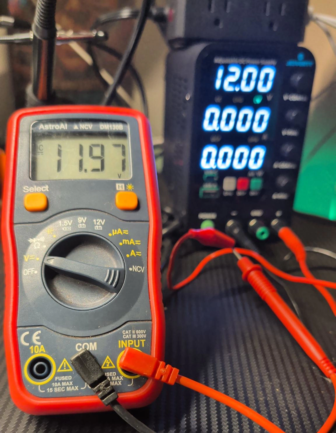
A reading is a measurement, not the truth. The supply says 12.00V, the meter
says 11.97V, and both are right. Every instrument has a tolerance, and 0.03V at
12V is 0.25% — comfortably inside a cheap meter's spec, which is usually
something like ±0.5% plus a count or two. The supply's own display is just
another readout with its own error, so “12.00” is not ground truth either.

A few things feed the gap:

  — Meter tolerance. At 12V, ±0.5% is ±0.06V, so anything from about
    11.94 to 12.06 is a “correct” reading on this meter. 11.97 is dead centre.
  — Supply tolerance. The PSU's set-point and its display each carry error
    too; the number on its screen is not a calibrated reference.
  — Resolution and rounding. The meter shows hundredths and rounds to
    them, and the last digit always wanders a count or two.
  — Calibration drift. Cheap gear ages and drifts, and neither box has
    seen a lab standard lately.

What is not in play here is loading. A voltmeter has a very high input
impedance (~10MΩ), so it draws almost no current and barely disturbs the
source — the reading is the real open-circuit voltage. (Lead resistance only
bites when current actually flows, which is why it matters for the current
and battery-test readings, not this one.)

The lesson: don't chase the last count. For bench work you want a meter that is
consistent and close, not one that matches another box's final digit. When you
truly need absolute accuracy, that is what a calibrated reference is for.
[ Continuity and resistance ]
Turn to the Ω · ⓑ · diode position and press Select to pick which of the
three you want. Do all of this with the circuit powered off.

  — Continuity (the sound-wave symbol): touch the probes together and it
    beeps. Now the beep means “these two points are connected.” It is the
    fastest test you own — a blown fuse goes silent, a good wire beeps, a
    switch beeps when closed, a cracked trace stays quiet. Most debugging is
    just this.
  — Resistance (Ω): reads the resistance of whatever is between the
    probes. A resistor reads its value; the NTC thermistor on a BMS reads a
    few kΩ and changes as you warm it with your fingers. OL (or a lone
    1 on the left) means over-range — an open circuit, infinite
    resistance. Measure parts out of circuit; in-circuit, other paths in
    parallel throw the reading off.
  — Diode (the arrow-and-bar symbol): red on the anode, black on the
    cathode shows the forward drop — about 0.5–0.7V for a silicon diode,
    1.8–3V for an LED (which will glow faintly). Backwards reads OL. Good for
    finding a diode's polarity or a dead LED.
[ The battery-test positions ]
The 1.5V, 9V and 12V marks are a genuinely useful shortcut. A plain
voltage reading is taken with nothing drawing from the battery, so a nearly-dead
cell can still read its full voltage — right up until you put it under load and
it collapses. These positions apply a small load and show the voltage under
it — the number that actually tells you whether the battery is any good.

Pick the mark that matches the battery's nominal voltage, red in INPUT and
black in COM, red to + and black to −:

  1.5V   AA, AAA, C, D, button cells
  9V    the rectangular 9V block
  12V   a 12V pack, a car battery, or the 3S pack from the BMS guide

A healthy battery holds near its rating under the test load; a tired one reads
noticeably lower than it did unloaded. That gap is the whole point.
[ Measuring current (the careful one) ]
Current is the measurement people reach for least and get wrong most, so treat
it deliberately. Re-read across vs. in series first: current means
breaking the circuit and putting the meter in the gap.

  1. Power the circuit down before you rewire it.
  2. Open the circuit at one point — unplug a wire, lift one end of a load.
  3. Put the meter in the gap: one probe to each side of the break, so the
     current has to flow through the meter to complete the loop.
  4. Pick the jack and range for the size of current:
       — up to a few hundred mA: red stays in INPUT, dial to µA or mA.
       — more than that: red moves to the 10A jack, dial to A. That jack
         is 10A for 15 seconds only — it is not a place to linger.
  5. Power up, read, power down, and put the red lead back in INPUT.

If you are not sure how much current to expect, start on the 10A jack so a
surprise doesn't blow the smaller fuse. And never, ever leave the meter in a
current mode and then go probe a voltage — that is rule 2, and it is the fuse's
last moment.
[ NCV, hold, and the backlight ]
Three conveniences worth knowing:

  — NCV (non-contact voltage): turn here and hold the top of the meter
    near a wire or outlet. It beeps and flashes when AC mains voltage is
    nearby, without touching a thing — the quick “is this wire live?” check
    before you work on it. It only senses AC, so it says nothing about a DC
    battery, and it is a warning light, not a measurement.
  — Hold (the H button): freezes the current reading on the display so
    you can move the probes off and then look. Press again to release. Handy
    when the contacts are somewhere you can't watch the screen.
  — Backlight (the sun icon on the same button): lights the display for
    working in a dim enclosure or under a dash.
[ What goes wrong ]
Ranked by how often it bites.

  leads in the amps jack   Left the red lead in 10A (or the dial on A) after
                       a current measurement, then probed a voltage. Dead
                       short through the meter, blown fuse. Always reset to V
                       and INPUT when you finish.
  in-circuit resistance   Measuring a resistor or a part while it is still
                       soldered in a live-ish circuit. Parallel paths and any
                       remaining charge give a meaningless number. Power off,
                       and isolate the part when it matters.
  reading the unit wrong  The number is right but the display says mV
                       or kΩ, not V or Ω. Auto-ranging moves the decimal for
                       you; read the unit, not just the digits.
  OL / 1 panic            OL, or a lone 1 on the left, is not a fault —
                       it is over-range: an open circuit, or a value past the
                       scale. On continuity it just means “not connected.”
  dead meter battery      Blank, dim, or drifting readings are often the
                       meter's own coin or 9V cell, not your circuit. Rule it
                       out before you chase a ghost.
  over the rating         This is a CAT II 600V / CAT III 300V pocket meter.
                       It is right for batteries, boards and household outlets
                       with care — not for poking around a breaker panel.

None of these are hard once you have met them. The meter is nearly
indestructible if you keep the black lead in COM, keep the red lead in INPUT
unless you are on purpose measuring amps, and never bridge a voltage in current
mode.