
[ Wiring a Daly BMS into a DIY 12V 18650 Pack ]
[ Overview |
What "12V" means |
What the BMS does |
Picking the board |
The cells |
Balance taps |
Wiring order |
Verify it |
Charging |
Fusing |
What goes wrong |
The build |
Going to 24V ]
[ Overview ]
This builds a 12V pack: three 18650 cells in series, which is 3S in
battery shorthand. Every voltage, tap, and part number below is the 3S case. If
you want 24V instead, the wiring is identical and only the arithmetic changes,
which is what Going to 24V at the end covers.

Three 18650 cells in series give you a 12V-ish pack for about the price of a
sandwich, and a BMS is the small red board that keeps that pack from
becoming an interesting evening. It watches each cell individually, cuts the
circuit when one goes too high or too low, trips on over-current, and nudges the
cells back into agreement over time.

Wiring one in is not hard, but the parts that are hard fail quietly. Two
mistakes in particular give you a pack that works perfectly on the bench and is
completely unprotected: hanging the load off the wrong terminal, and getting the
balance-wire order wrong. Both are covered below.

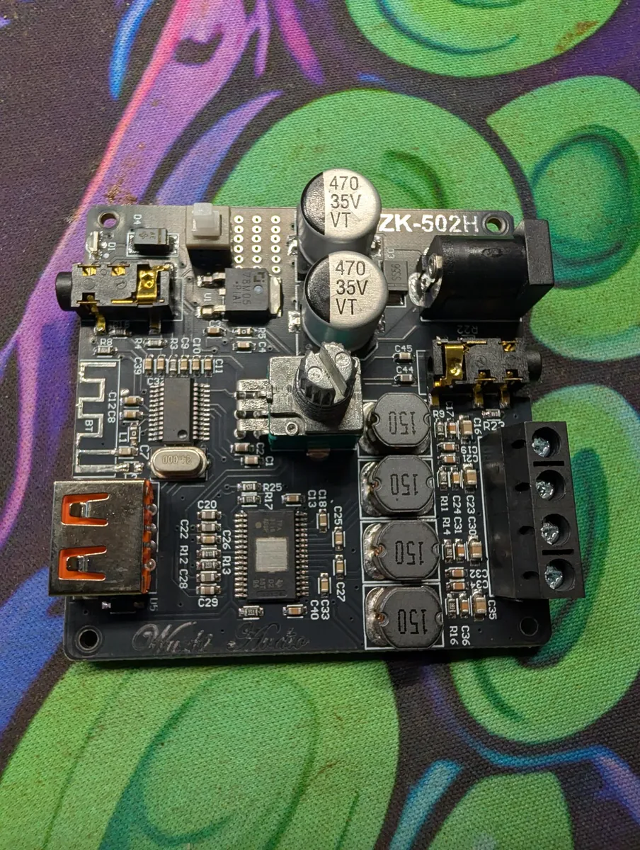
The worked example is a portable speaker: 3× 18650, a Daly
Mini-red 3S 20A board, and a TPA3116D2 class-D amp. The method is the
same for any small Daly board and any cell count; only the tap ladder gets
longer.

Safety, once, plainly: a shorted 18650 dumps tens of amps into whatever is
across it and gets hot enough to start a fire. Work one connection at a time,
insulate as you go, and never leave a half-built pack unattended on the bench
with bare leads.
[ What "12V" actually means here ]
Lithium-ion cells are 4.2V full, 3.7V nominal, and flat somewhere around 3.0V.
Three in series (3S) puts you at:

  full        12.6 V     4.2 V / cell
  nominal     11.1 V     3.7 V / cell
  empty        9.0 V     3.0 V / cell

So a "12V" 3S pack sits above a lead-acid battery when full and well below one
when flat. Most 12V gear is happy with that, since it is designed to survive a
car's 9V cranking dip. Anything with a hard brownout above 10.5V will cut out
while the pack still has real capacity left.

If you want a genuine lead-acid drop-in, the answer is 4S LiFePO4, not 3S
lithium-ion: 14.6V charge, 12.8V nominal, and a flat discharge curve that sits
right on 12V for most of the pack. It costs more and it is a different BMS. Pick
the chemistry first, then buy the board to match it.
[ What the BMS actually does ]
A BMS is four things in one package:

  per-cell cutoff   opens the circuit when any single cell goes over
                    ~4.25V or under ~2.5–2.8V
  over-current      opens on a sustained overdraw, and much faster on a
                    dead short
  temperature       opens on an over-temp reading from the NTC probe, and
                    blocks charging below freezing
  balancing         bleeds the highest cell through a resistor during
                    charge so the pack drifts back together

The one thing to internalise: the board switches the negative leg only. Pack
positive is a pass-through. It never goes anywhere near the MOSFETs.

  ┌──────────┐
  │          │  B+ ────────────────────────────▶  load +  /  charger +
  │    3S    │      (not switched: the BMS is not in this leg)
  │  18650   │
  │   pack   │       ┌──────────────────────┐
  │          │  B− ──┤  BMS  [ MOSFETs ]  P−├──▶  load −  /  charger −
  └──────────┘       └──────────────────────┘
                      every cutoff you paid for happens here

That is the whole idea in six lines; the full schematic further down draws
the same thing with the balance taps, the NTC and the charger in place.

That layout is why the single most common wiring mistake is invisible. If you
run the load's negative to B− instead of P−, everything lights up and
sounds fine, and you have simply built a pack with no protection at all. The
board sits there balancing and reporting while the current goes around it.
[ Picking the board ]
Four numbers decide which board you order, and one of them is not negotiable.

  chemistry    Daly sells the same physical board in lithium-ion (4.2 V /
               cell) and LiFePO4 (3.65 V / cell) versions. They are not
               interchangeable. A LiFePO4 board on a Li-ion pack cuts off
               far too early; a Li-ion board on a LiFePO4 pack never cuts
               off at all. Read the model code, not the picture.
  cell count   3S here. The board must match exactly; the balance
               connector has one more wire than there are cells.
  current      Size it above your real peak, not your average. Headroom is
               cheap and the trip point is not your fuse (see below).
  port type    Common port means one P− shared by the charger and the
               load, which is the simple case and what the diagram above
               shows. Separate port splits it into C− for the charger
               and P− for the load, usually because the board's charge
               rating is much lower than its discharge rating.

The Mini-red used here is a common-port 3S 20A lithium-ion board, which is
absurd headroom for a speaker amp and exactly the right call: it means the
over-current circuit never nuisance-trips on a bass transient.

The board also ships with a small NTC thermistor on its own two-pin plug.
Leave it plugged in and tape the bead to a cell body, not to the board. Charging
lithium-ion below 0°C plates metallic lithium inside the cell, which is
permanent and genuinely dangerous, and the NTC is the only thing that knows.
Many of these boards also refuse to enable their output with the probe missing
or reading open.
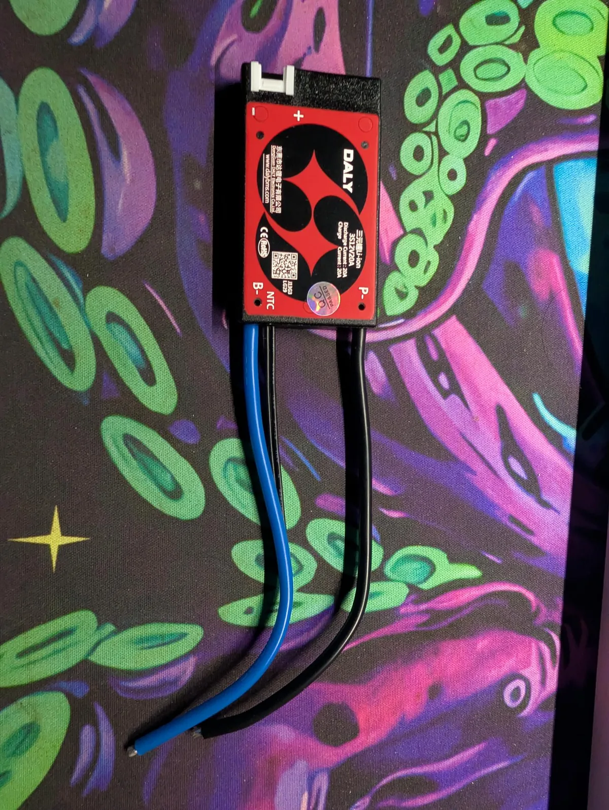
3S12V20A, 20A charge and discharge. The white plug up top is the balance connector (the four-wire ladder); the blue and black leads are B− and P−, and the NTC pads take the temperature probe.[ The cells ]
A series pack is only as good as its worst cell, because that cell hits the
cutoff first and defines the whole pack's usable capacity. The BMS balancer
trickles at something like 30–100 mA and corrects drift over many cycles. It
will not rescue a pack you built out of mismatched cells.

  — Same everything. Same brand, model, capacity, and roughly the same
    age and cycle count. Never mix a new cell into an old group.
  — Test before you build. Capacity-test every cell and note the internal
    resistance if your charger reports it. Anything that reads well off the
    group's average does not go in.
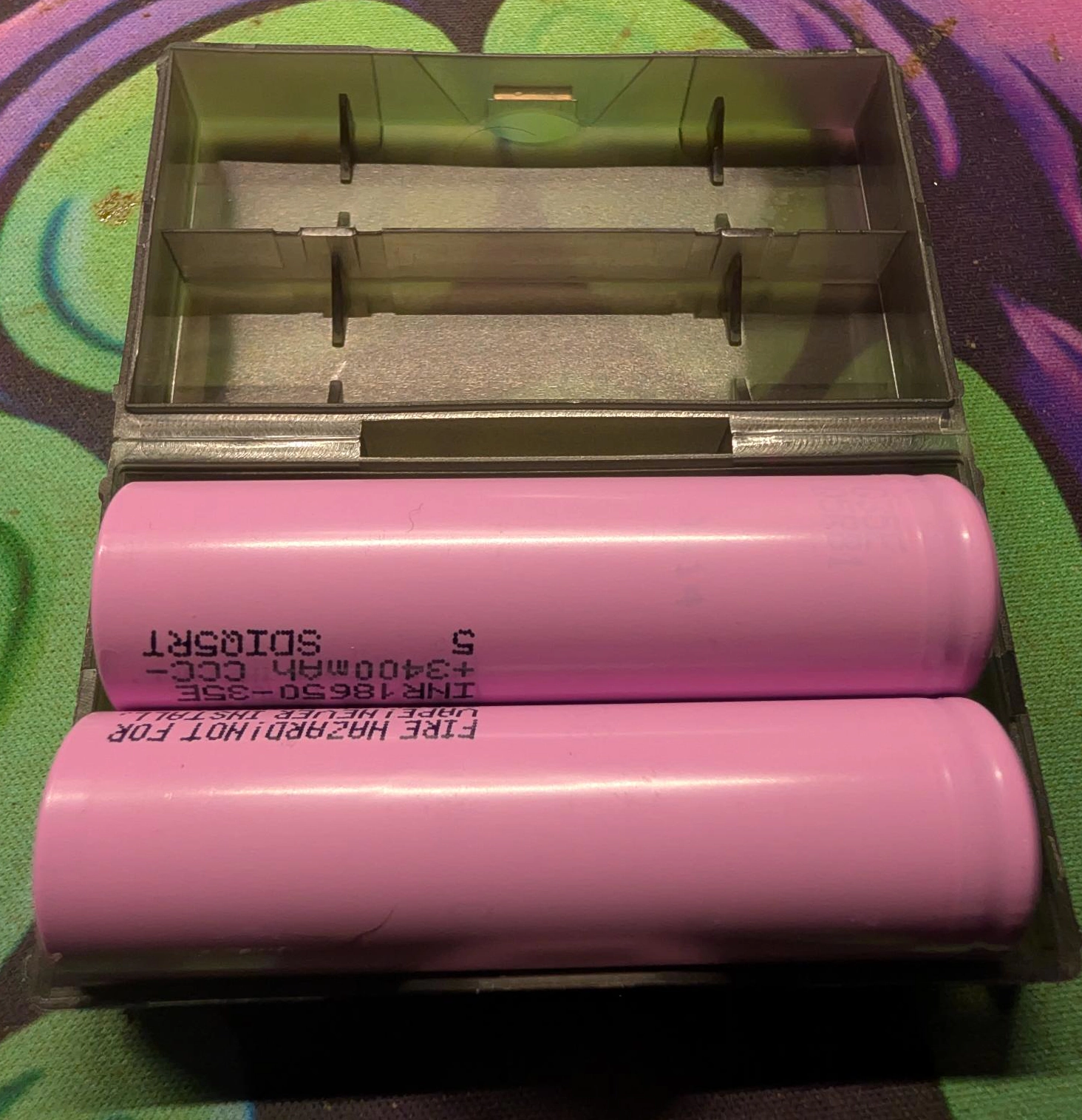
  — Ignore the wrapper. A real 18650 tops out around 3500 mAh — a
    Samsung INR18650-35E (3500 mAh, 8A) is about as much as the chemistry
    gives in this size. Anything claiming 9900 mAh is a re-wrapped 800 mAh cell
    with a sticker. lygte-info.dk has independent discharge curves for most
    cells worth buying, and for a lot that are not.
  — Start them level. Charge each cell individually to the same voltage
    before you wire them in series, then let them sit overnight and measure
    again. A cell that has sagged noticeably has a self-discharge problem and
    is out.

For assembly, spot-welded nickel strip is the correct answer. If you are
soldering to cells anyway, use a large iron so the joint is done in two or three
seconds, abrade and flux the terminal first, and never park the tip on a cell.
Fish-paper insulating rings on the positive ends are worth the pennies: the
outer ring of the positive terminal is the can, which is negative, and one nick
in the wrap there shorts the cell against its neighbour.
[ The balance taps ]
The balance connector is how the board sees each cell separately. A 3S board has four wires: one at pack negative and one at every junction going up. The most-negative wire is usually the thin black one, and silkscreens vary betweenB0…B3andB1…B4for the same board, so identify it by position, not by the printed number. ●───────────────────── B4 pack + 12.6 V │ ┌──┴─────┐ │ cell 3 │ └──┬─────┘ ●───────────────────── B3 cell2 + / cell3 − 8.4 V │ ┌──┴─────┐ │ cell 2 │ └──┬─────┘ ●───────────────────── B2 cell1 + / cell2 − 4.2 V │ ┌──┴─────┐ │ cell 1 │ └──┬─────┘ ●───────────────────── B1 pack − 0 V (reference) The voltages on the right are what you should measure from pack negative with every cell at 4.2V. It is a ladder: each step up is one more cell, and every step should be positive and about the same size as the others. Order matters and mistakes are fatal to the board. Each sense input expects to see roughly one cell above the one below it. Connect out of order, or plug the connector in while the pack is only half-assembled, and you can put the full pack voltage across an input that expects a few volts. Connect the pack-negative wire first, then work upward one tap at a time, and measure the ladder before the connector goes anywhere near the board. If a step reads negative, a cell is in backwards. If a step reads zero, two taps are on the same node. Fix it on the bench, not by plugging it in to see.
[ Wiring order ]
Do it in this sequence. Each step assumes the previous one checked out.

  1. Build and check the pack. Cells in series, positive to negative, and
     measure the tap ladder from pack negative: 0, ~4.2, ~8.4, ~12.6.

  2. Balance leads on, bottom-up. Pack negative first, then each junction
     in order, then pack positive last.

  3. Plug in the NTC. Bead taped to a cell, not the board.

  4. Connect B−. Pack negative to the board's B− terminal. Heavy
     gauge and as short as you can make it: this carries full pack current
     and is the reference the board measures everything against. A long thin
     B− lead makes the board see a sagging pack under load and nuisance-trip.

  5. Connect P− to the loads. Amp negative and charger negative both land
     here. On a common-port board they share the terminal.

  6. Connect B+ to the loads. Pack positive straight to amp positive and
     charger positive, through the inline fuse. This leg does not touch the
     BMS.

Insulate each joint as you make it rather than at the end, and keep the balance
leads routed away from the main current path so they cannot get pinched under
the board when everything goes in the enclosure.
[ Verify it before you trust it ]
Four measurements, a minute of work, and they catch every mistake above.

  B+ to B−       pack voltage, whatever the cells add up to
  B+ to P−       the same number. Equal readings mean the MOSFETs are
                    conducting and the board is awake.
  each cell        3.0–4.2V, and all three within about 0.05V of each
                    other
  under load       switch the load on and watch B+ to P−. It should sag a
                    little and stay there, not collapse to zero.

If B+ to P− reads zero or some odd fraction of pack voltage, the board is
either in protection or asleep. Many of these boards ship dormant and wake on
the first sight of a charger, so touch the charger to it before assuming the
board is dead.

The check that matters most is the second one, and it only proves the board is
conducting. It does not prove you wired the load to the right terminal, since
B− and P− read the same when nothing has tripped. Trace the load's negative
wire with your eyes and confirm it lands on P−.
[ Charging ]
A 3S lithium-ion pack wants a CC/CV supply that terminates at 12.6V. Constant
current until the pack reaches 12.6, then constant voltage while the current
tapers off, then stop.

  — A plain 12.0V wall wart will never fill the pack. It is not a charger.
  — A 12V lead-acid charger floats at 13.8–14.4V, which is 4.6–4.8V per
    cell. That leaves the BMS as the only thing between you and an
    overcharge, on every single charge cycle.
  — A 14.6V LiFePO4 charger is worse for the same reason. Different
    chemistry, different voltage, do not mix them up.

Charge current at 0.5C is comfortable, so a single 3000 mAh cell per series
position takes about 1.5A. Faster works and shortens cell life.

Balancing on a small passive board only happens near the top of the charge, so a
pack that lives at half charge and never finishes a cycle will slowly drift
apart. Run it to full occasionally and let it sit on the charger for a while
after the current tapers.
[ Fusing ]
The BMS is not a fuse and it was never trying to be one. A 20A board trips near
20A, which is there to protect the cells and its own MOSFETs from a dead short.
It will happily pass 15A through a pinched wire feeding a 3A amp until something
melts.

Put an inline fuse on the B+ leg, sized just above your real peak draw, as
physically close to the pack as it will go. The wire between the cell terminal
and the fuse is the only copper in the build that nothing protects, so the
shorter it is the better. A blade fuse holder or a ceramic cartridge both work;
what matters is that it exists.

The wire itself: size the main leads — B+, B−, and P− — to the
board's rating, not your load, so they are never the weak link. For a 20A board
that is 14 AWG at a minimum, 12 AWG for comfort, in silicone-insulated
stranded wire (flexible, high-temp, and what the board's own leads already are).
All three carry the same full current, so use the same gauge on each. The
balance wires are the opposite — they only sense voltage and pass the tiny
balancing current, so the thin JST harness the board came with is correct; don't
beef it up.

For the speaker build here, the amp's real draw peaks well under 5A at this rail
voltage, so a 6A fuse gives normal operation plenty of room and still opens
long before the BMS notices anything is wrong.
[ What goes wrong ]
Ranked by how often it happens and how quietly it fails.

  load on B−       The classic. Works perfectly, protects nothing. You
                     find out the first time the pack over-discharges and a
                     cell never comes back.
  balance order     Connector plugged in out of order or with the pack
                     half-built. Usually kills the board outright, and
                     occasionally does it silently so the board only stops
                     reading one cell correctly.
  wrong chemistry   A LiFePO4 board or charger on a lithium-ion pack, or
                     the reverse. One direction gives you a pack that seems
                     to have no capacity; the other gives you an overcharge.
  NTC unplugged     No output at all on some boards, and on the rest, a
                     charge into a frozen pack with nothing watching.
  long thin B−     Voltage drop under load looks like a sagging pack to
                     the board, so it trips early and you chase a fault that
                     is really just wire gauge.
  no fuse           Covered above. The BMS trip point is not protection
                     for your wiring.
  reset and retry   A BMS that trips is telling you something. Clearing it
                     and carrying on without finding out which cell went out
                     of range is how a marginal cell becomes a fire.

A tripped board usually clears on its own once the fault condition goes away, or
after a moment on the charger for an under-voltage trip. That is a diagnostic
step, not a fix.
[ The build it came from ]
A portable speaker, running entirely off one 3S pack:

  cells          3× 18650 in series
  BMS            Daly Mini-red, 3S, 20A, common port, lithium-ion
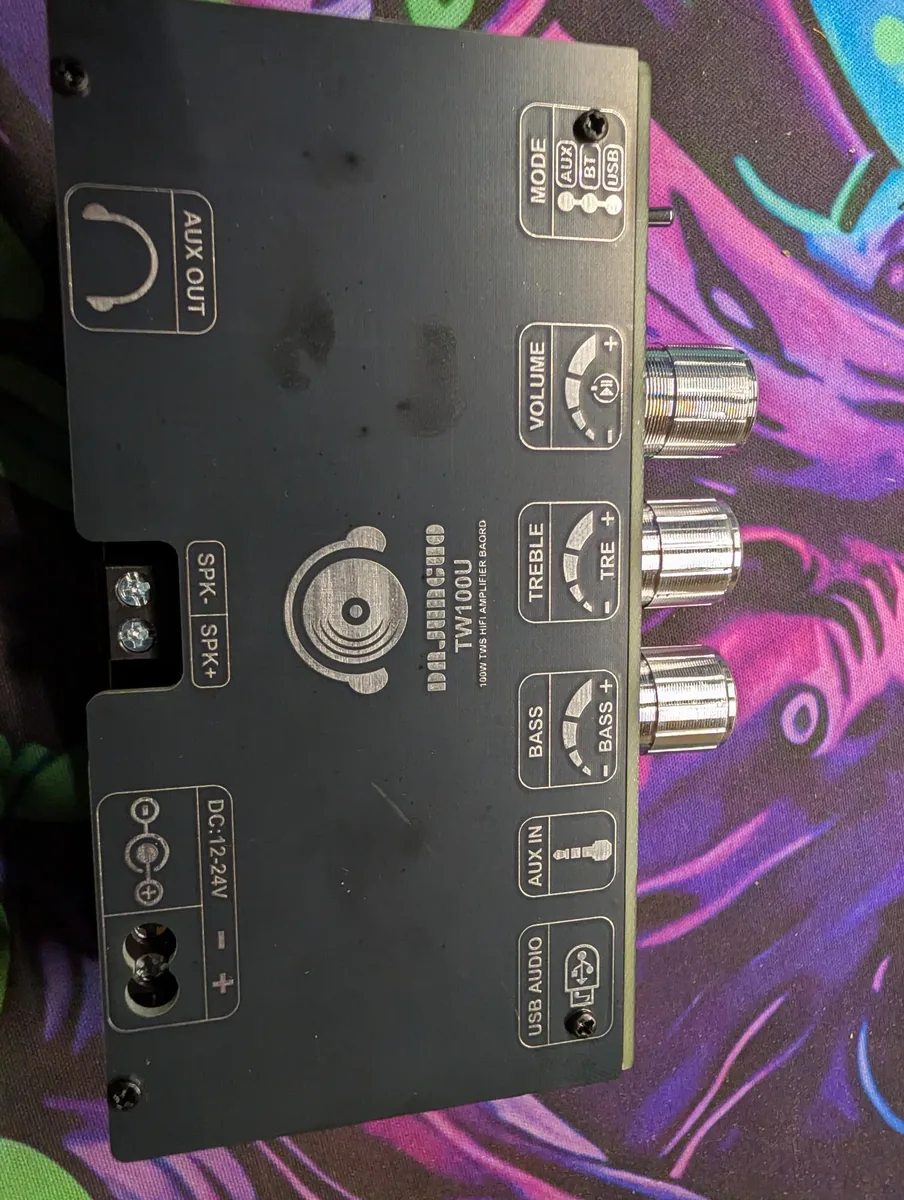
  amp            TW100U mono (TPA3116D2 class-D), 12–24V input
  driver         DS18 G4Xi, 4Ω, 40W
  charge         12.6V CC/CV to a barrel jack, sharing P− with the amp
  protection     6A inline fuse on B+, at the pack

The load hardly matters to the pack here, since a few amps on a 20A board is
nothing. What does matter, on anything you hang off a 3S pack, is the load's
minimum input voltage. Gear labelled "12V" is being fed 11.1V nominal and 9V
at the bottom, so read the low end of its range and find out where it actually
browns out before you close up the enclosure. If it quits early you lose most of
the pack, and that is the argument for going up a cell.

Everything above is the 12V case. The order, the checks, and the two mistakes
that matter do not change with cell count, so going up is mostly arithmetic.
[ Going to 24V ]
Two different questions hide behind "24V", and they have different answers.

                       3S             4S             6S

  cells in series      3              4              6
  full                 12.6 V         16.8 V         25.2 V
  nominal              11.1 V         14.8 V         22.2 V
  empty                 9.0 V         12.0 V         18.0 V
  balance wires        4              5              7
  top of ladder        12.6 V         16.8 V         25.2 V
  charger              12.6 V         16.8 V         25.2 V
  100 W at nominal     ~9.0 A         ~6.8 A         ~4.5 A

6S is the literal 24V pack. Six cells is 25.2V full and 22.2V nominal, which
is the lithium-ion equivalent of a 24V lead-acid rail and what you want if you
are feeding gear designed around one.

But "24V" on a datasheet is usually a ceiling, not a target. When a board says
12–24V input, that 24 is the number you must not exceed, and a 6S pack is
25.2V straight off the charger. It is over the line before you have played a
note. For that case the answer is 4S: 16.8V full, well under the ceiling, and
it still buys you most of what you wanted.

4S also fixes the other end of the range. It is 16.8V full and 12.0V empty, so
it sits at or above a 12V minimum across the entire usable discharge, where a
3S pack drops under 12V almost immediately. For anything spec'd 12–24V, 4S is
the pack that actually stays in the window at both ends.

5S is a related aside, not a 24V option. Five cells (21V full, 18.5V
nominal) is the tool-battery voltage — a 20V DeWalt is 5S on the inside. Daly
makes 5S boards too; wiring a 5S pack is its own guide, Wiring a 5S BMS.
Why go up at all: current. Power is volts times amps, so a 100W load pulls
about 9A at 3S, 6.8A at 4S, and 4.5A at 6S. Wire gauge, fuse rating, connector
choice, BMS current rating, voltage drop down a long run, and heat in the wiring
all come down together. On anything drawing real current, or sitting at the end
of a few metres of cable, higher voltage is the better build.

Four things change, whichever you pick:

  — The board. A BMS with the matching cell count, not a 3S board with
    extra cells hung off it. 4S takes a five-wire balance connector, 6S takes
    seven.
  — The ladder gets longer. Measured from pack negative with every cell
    full, 4S is 0 / 4.2 / 8.4 / 12.6 / 16.8V and 6S is 0 / 4.2 / 8.4 / 12.6 /
    16.8 / 21.0 / 25.2V. Same rule as before: bottom-up, one at a time,
    measured before the connector goes near the board. More taps is more
    chances to get it wrong, and the top of a 6S ladder sits at 25V rather
    than 12.6, so a mis-ordered connection has more energy behind it.
  — The charger. 16.8V or 25.2V CC/CV, matched to the pack. Not a
    nominal-voltage supply, which never fills it, and not a lead-acid charger,
    which floats high enough to work out well past 4.2V per cell.
  — Inrush. 25V into a load with big input capacitors makes a real spark
    on connection, enough to pit connector contacts and occasionally trip the
    BMS on the way in. If that is your load, put a precharge resistor across
    the switch or use a connector rated for it.

Bigger packs are usually 4S2P, 6S2P or 6S3P, because one cell per
series position is not much runtime. The BMS still only sees four or six cells:
each one is now a parallel group, and the balance tap lands on the group, not on
an individual cell. Cells inside a group must be matched and sitting at the
same voltage before you join them. Paralleling a full cell to a half-empty one
dumps a large uncontrolled current between them through whatever nickel strip is
in the way. Charge everything to the same point first, build the parallel
groups, then put the groups in series.

Everything else is identical. B+ still bypasses the board, the load still lands
on P−, the NTC still has to be plugged in, and the fuse still goes on the B+
leg at the pack.

Going up in voltage also opens the door to a cheap add-on the 12V build can't
use: an XH-M609-style low-voltage disconnect, a relay board with a voltage
display that cuts the load below a threshold you set. It is a nice second layer
and a handy voltmeter, but its logic needs about 12V to run, so it suits 4S
and 6S comfortably and is wrong for the bare 3S pack here: a 3S pack empties
at 9V, well under the board's floor, so it would brown out before it ever
protected anything. On 3S, lean on the Daly's own cutoff, or use a
lower-voltage LVD. (The tool-battery guide uses one of these on a 5S pack.)

If you want a true 24V lead-acid drop-in rather than a 24V-ish lithium-ion pack,
the answer is 8S LiFePO4: 29.2V charge, 25.6V nominal, 20V empty, and a flat
curve that sits near 25V for most of the pack. Same reasoning as 4S LiFePO4 at
12V, and the same rule about buying the board to match the chemistry.
[ See Also ]
Battery Pack Calculator # size the pack (voltage, Ah, Wh, current) before you build it
Using a Basic Multimeter # the meter behind every "check" in this guide
Wiring a 5S BMS (20V) # the same build at 5S — a roll-your-own tool battery
Using a Power-Tool Battery # the buy-it-engineered alternative to rolling your own
ESP32 Getting Started # the three ways to power a board, and the 3.3V rules
DIY Power over Ethernet # the other cheap way to get power where you need it
Calibrating 3D Printer Filament # dial the printer in before you print the enclosure
Meshtastic Node Build # battery and solar sizing for a node that lives outside
lygte-info.dk # independent 18650 discharge curves and capacity tests