[ Using a Power-Tool Battery as a Power Source ]
[ Overview |
What "20V" means |
The terminals |
Cell health |
Tapping power |
Does it need waking? |
Powering your load |
Protection & fusing |
Other brands |
What goes wrong |
Buy vs. build ]
[ Overview ]
A 20V DeWalt battery is a rugged, well-engineered lithium-ion pack with its
own protection board, a charger you already own, and a case built to be thrown
in a truck. That makes it a tempting power source for anything portable: a
field radio, a Meshtastic node, LED lighting, a 12V pump, a Raspberry Pi in a
box. You clip the pack on, pull power off two terminals, and pop it back on the
charger when it is flat.

The catch is that the pack was designed to talk to a tool, not to you. Its
terminals are unlabelled to the naked eye, only two of them carry power, the
bare blades can dump a frightening amount of current into a short, and whether
the pack even turns on without the tool depends on the brand. None of that is
hard once you know it, and this guide walks the whole path.

The worked example is a DeWalt 20V MAX pack, because it is the most common
and the friendliest (it just works on two wires). The Other brands section
covers where Milwaukee, Makita and Ryobi differ.
Safety, once, plainly. A tool pack can dump 30 to 60 amps into a
dead short without flinching — enough to weld a dropped screwdriver, ring, or
watch strap to the terminals, heat the metal red-hot against your skin, and
start a fire. At 20V the hazard is that current, not shock: 20V is too low to
shock you through dry skin, but the burn it drives is not. Bigger series packs
and FlexVolt's 60V mode do climb into voltages that can shock. So: lose the
metal jewellery, keep the blades covered until you are wired, fuse the positive
leg at the pack, and never leave bare terminals exposed on the bench.
[ What "20V" actually means ]
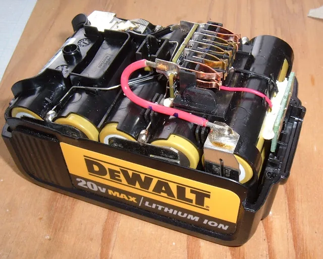
"20V MAX" is a marketing number. The pack is five lithium-ion cells in
series (5S), and five cells do this:

  full        21.0 V     4.2 V / cell   (the "20V MAX" peak)
  nominal     18.0 V     3.6 V / cell   (the honest average)
  empty       15.0 V     3.0 V / cell

That is why the exact same DeWalt pack is sold as 18V XR in Europe: 20 is the
peak off the charger, 18 is the number it spends most of its life near. They are
the same battery with a different sticker.

The practical consequence: design your project for the whole 15 to 21V band,
not for 20. A load that needs a clean 12V, or 5V USB, gets a buck converter;
a load that tolerates 15 to 21V directly can take the pack as-is.

Most cordless-tool platforms in this class are 5S and behave the same way:
Milwaukee M18, Makita 18V LXT, Ryobi ONE+ 18V, Bosch 18V. DeWalt's FlexVolt
packs are the exception and get their own note below.
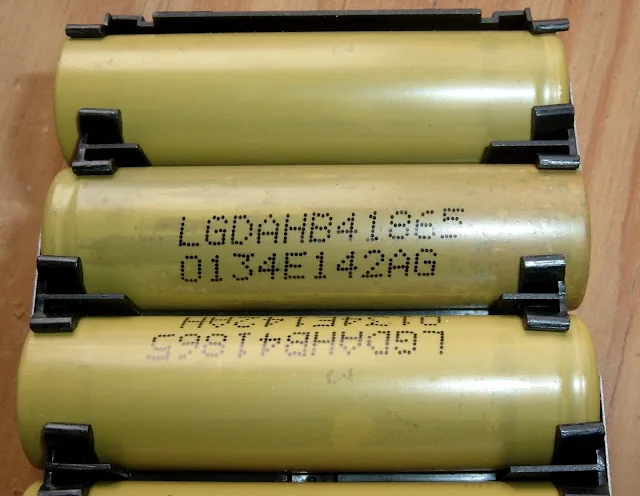
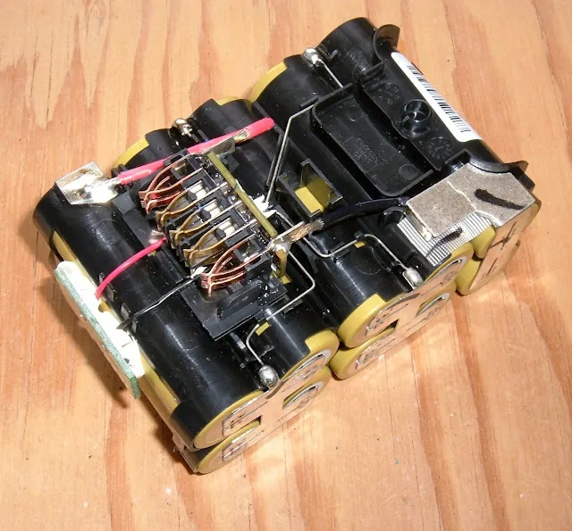
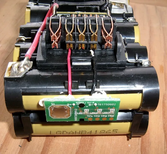
LGDAHB41865). Tool packs favour high-drain cells like these — built to deliver the big current a saw or drill pulls, rather than to maximise capacity. That is the opposite priority from a high-capacity cell like the Samsung 35E; a tool wants amps.[ The terminals ]
Look at the end of the pack that clips onto the tool and you will see a row of
flat blade terminals in a plastic slot. Only two of them are power. The rest run
to the pack's control electronics.

  — B+ and B−  the two power terminals. Usually the outermost
    pair, and often physically heavier than the rest, because they carry the
    full tool current. These are the only two you connect.
  — Thermistor  a terminal wired to an NTC inside the pack so the tool
    (and charger) can read cell temperature. You leave it alone.
  — ID / data  some packs have an identification or data line the tool
    uses to recognise the battery. Also left alone.

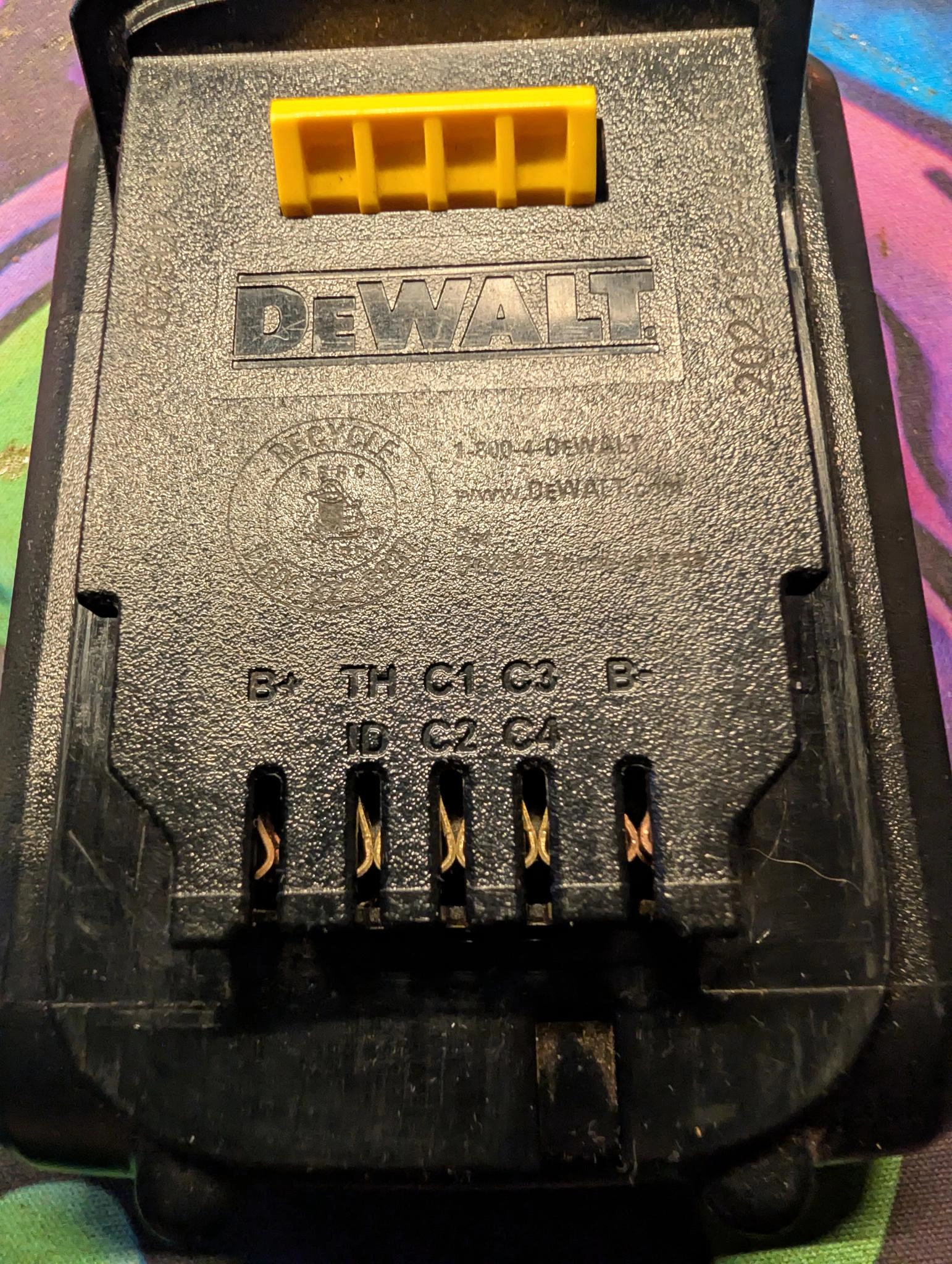
A genuine DeWalt 20V MAX pack actually spells this out, in faint molded
letters across the terminal end: B+ and B− at the two ends, TH
(thermistor) and ID between them, and C1–C4 — the four cell-junction
taps the charger reads to watch the five cell groups while charging. It confirms
the rule: a row of control terminals, and only the two on the ends carry power.

The catch is that clones and other brands relabel or reorder all of this, and on
a worn pack the letters are unreadable anyway. So do not trust the labels or
the position — find the power pair with a meter, every time:
[ Reading cell health from the outside ]
Those C1–C4 taps earn a section of their own, because they are not only for
the charger: each one sits on a cell-group junction, so a meter on them reads
the voltage of every group in the pack. You can check a used or unknown pack's
balance and health from the terminals, without ever opening it — the best
five-minute test there is before you trust a battery.

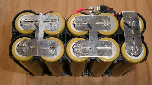
A 20V MAX pack is 5S2P: five groups of two parallel 18650s, ten cells in
all, which is why this is about cell groups, not single cells. The five group
voltages stack up the ladder to the pack total.
How to read them. Meter on DC volts, black lead on B− and left there;
walk the red lead up the taps: B−, C1, C2, C3, C4, B+. Each reading is
cumulative from the bottom, so subtract each from the one before it to get
that group's voltage. The multimeter guide covers the meter side.
Here is a healthy pack, fully charged, beside a failed one straight off the
charger — each group is the difference between two consecutive taps:

                     healthy pack    failed pack
  group 1  (C1)        4.08 V          4.08 V
  group 2  (C2)        4.09 V          0.02 V   dead
  group 3  (C3)        4.09 V          4.09 V
  group 4  (C4)        4.08 V          4.00 V
  group 5  (B+)        4.09 V          4.18 V   high
  ---------------------------------------------
  pack total          20.43 V         16.37 V
  balance             within 0.01 V   one dead group

The healthy pack holds every group within 0.01V — that tight a spread is a
well-balanced pack in good shape, exactly what you want to see. Notice the
groups sit at ~4.1V, not the 4.2V of a fully-charged lithium-ion cell:
DeWalt stops a hair short of 100% on purpose. A true full charge is hard on
calendar life, and tool packs mostly live on the shelf charged, so the
slightly-low target buys shelf longevity.

The failed pack tells its story in one column. Group 2 has collapsed to
0.02V — a dead group — and with it gone the charger has shoved the survivors
out of balance, one up to 4.18V. A pack with a collapsed group is done:
recycle it, do not keep charging it. Charging around a dead or reversed group
is how a bad battery becomes a fire.

That is the worst-cell rule made visible — a series pack is only as good as
its weakest group — except here the taps let you find the weak one from the
outside in under a minute. It is also a quiet argument for these packs: cell
health you can verify externally beats a sealed brick you have to trust.

An aside on the charger. On the charger's own contacts, the pin that meets the
pack's ID terminal is a hair longer than the rest and sits at low potential,
and the charger's pins carry a floating voltage with no pack present. That
points at ID being a wake line — pull it low and the charger comes alive —
but that is a hypothesis, not worth probing on a charger you rely on.
[ Tapping power off the pack ]
Three ways to get from the terminals to a wire, easiest first:

  — Commercial adapter  a molded dock that clips on like a tool and breaks
    B+/B- out to screw terminals, a barrel jack, or USB. They cost a few
    dollars, contact only the two power blades, and are the right answer for
    almost everyone. Buy one rated for the current you need.
  — 3D-printed adapter  the same idea, printed, with salvaged tool
    contacts or brass inserts pressed in. Good if you want a custom shape or a
    built-in buck / fuse cavity. Print files for every major platform are all
    over the usual model sites; the filament-calibration guide helps if the
    contact slots come out too tight to grip.
  — Direct to the terminals  spade connectors or soldered tabs straight
    onto the blades. Works, but it is the easiest way to reverse polarity or
    bridge a terminal, and it leaves the pack modified. Prefer an adapter.

Whichever you use, it only ever touches B+ and B−. Nothing you build
connects to the thermistor or ID terminals. Those exist for the tool, and
back-feeding them does nothing useful and risks confusing a smart pack.
[ Does it need the tool to wake up? ]
This is the one behaviour that varies, and it is worth knowing before you design
around a pack.

Most common packs just work. DeWalt 20V MAX, and the majority of Milwaukee,
Makita and Ryobi packs, present full voltage on B+/B- the instant you connect,
with no handshake. That is exactly why the cheap two-terminal adapters exist and
sell by the thousand. Clip on, read voltage, pull current.

Some packs stay asleep. A few newer "smart" packs hold their output off until
they see a signal on a control terminal, or an initial current draw, and a few
cut the output after an idle period with no load. The symptom is unmistakable: a
meter reads full voltage across B+/B-, but the moment you connect a real load
the voltage collapses to zero, or it works for a while and then dies.

If you hit that, the pack wants the wake logic the tool provides. Options are to
add a small bleed resistor across the output to keep a trickle of current
flowing, to find and pulse the wake terminal (pack-specific, needs research for
your exact model), or to just use a simpler pack. For a first project, buy a
plain DeWalt 20V pack and skip the whole problem.
[ Powering your load ]
What you connect to B+/B- depends on what voltage your load wants.

  — 15–21V tolerant (many LED work lights, DC motors, and the input of
    any buck converter): connect straight to B+/B- through the fuse. The load
    sees the pack's real voltage, sagging from 21V down to 15V as it drains.
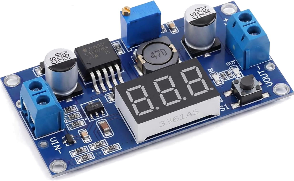
  — 12V gear: use a buck converter set to 12V. The common one is an
    LM2596 module (4–40V in, 1.25–37V out, with a trim pot and often a
    voltage display): feed it the pack, turn the pot until the display reads
    12V, done. Because the pack never drops below ~15V, the buck holds a
    rock-steady 12V across the entire discharge, cleaner than a nominal-12V
    lead-acid battery that starts at 12.6 and sags under load.
  — 5V USB: a USB / QC / PD buck module rated for a 21V input. Now the
    pack is a chunky power bank that charges on your tool charger.

Do not try to get 12V by tapping partway up the cell stack. The pack's
terminals only expose B+ and B-; there are no usable middle taps, and even if
there were, unbalanced draw across a series pack is how you cook cells. Step the
full pack voltage down with a converter instead.

Size the buck for both ends: enough output current for your load, and an input
rating comfortably above 21V. The LM2596's 40V ceiling clears the pack's 21V
with room, and it handles a couple of amps happily — but it warms up near its
3A limit, so a hungrier load wants a chunkier module (an XL4015 or a bigger
board). A converter maxed at "24V in" running at 21V all day runs hot; give it
margin, and add a heatsink if it is working hard.
[ Protection & fusing ]
A tool pack has its own BMS inside, which is one of the nice things about
using one: per-cell balancing and protection come built in, unlike a pack you
solder yourself. But that board is tuned for tool duty, and that changes what it
does and does not do for you.

  — It trips high. A pack rated to feed a 40A circular saw will not blink
    at 15A through a pinched wire in your 3A project. Its over-current
    protection protects the pack, not your wiring.
  — Its low-voltage cutoff usually lives in the tool. On most platforms
    — DeWalt, Milwaukee, Makita — the "stop before you damage the cells"
    logic is in the tool, not the pack, so a bare pack pulled directly can
    over-discharge further than a tool ever would. The exceptions are Ryobi
    and Ridgid 18V, which build the over-discharge cutoff into the battery
    itself — those self-protect, and you can skip the external cutoff below.
    Anything else: do not assume the pack saves itself.

So you still add:

  — An inline fuse on B+, right at the adapter, sized just above your real
    peak draw — the single most important part of the build, since the bare
    terminals sit on a source that can deliver tens of amps into a short.
    Estimate the load's peak (watts ÷ volts, or read it on a
    bench supply), add ~25% for inrush, and take the next standard fuse up:
    a ~3A load takes a 5A fuse, ~5A takes 7.5A, ~10A takes 15A. A blade
    holder or a ceramic cartridge both work.
  — Wire sized to the fuse, not the battery. The pack can source tens of
    amps, but the fuse caps what the load-side wiring ever carries, so size the
    adapter leads to the fuse, in silicone stranded: 18 AWG up to ~7A, 16 AWG
    to ~10A, 14 AWG to ~15A, 12 AWG to ~20A. The one stretch the fuse can't
    protect is the stub between the terminal and the fuse itself — keep that as
    short as the adapter allows. (Building the pack yourself is the other way
    round: there you size to the BMS rating, not the load.)
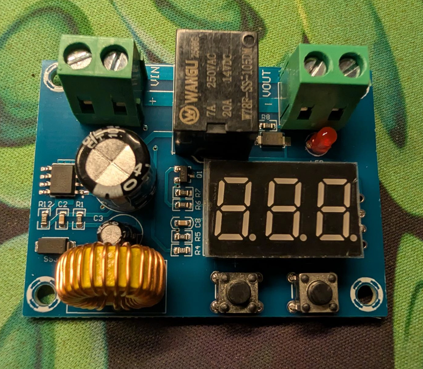
  — A low-voltage cutoff for anything that runs unattended. An
    XH-M609-style disconnect — a relay board with a voltage display and a
    12–36V range — wires straight inline: battery to its VIN, load to its
    VOUT. It shows the pack voltage on the display, and opens the relay when
    the pack falls below a threshold you set with the two buttons. For a 5S tool
    pack set the cutoff around 16–16.5V (about 3.3V/cell) and the reconnect
    a volt or so higher, so a battery that sags under load and recovers doesn't
    chatter the relay. Do not set it at the 15V floor: by ~15.3V a DeWalt
    pack is basically flat, and running the cells that low every cycle wears
    them out. Stopping at 16–16.5V also leaves headroom for sag — a pack
    resting at 16.5V can dip to 15V under load, so an earlier cutoff keeps the
    cells off the floor where it counts. That protects them from a slow
    drain the built-in board might let run too far: cheap insurance for a
    $100 battery.

    Two things to know about that board. Its relay sets the current ceiling
    (commonly 20A at ≤14V DC, derating above), so size it to your load. And
    the board itself draws a few milliamps to run its display and logic, so it
    guards against an over-discharging load, not against its own trickle
    — for long storage, unplug the pack rather than trusting the module to
    sit on it forever.
[ Other brands and the FlexVolt trap ]
The method is the same for every 5S platform; only the details move.

  — Milwaukee M18  5S, ~18V nominal, same as DeWalt electrically. Some
    M18 packs are chattier about wanting a signal, so meter-test wake
    behaviour before committing.
  — Makita 18V LXT  5S. The terminal block is busier (Makita does more
    in-pack monitoring), but B+/B- are still just two blades; find them with a
    meter as always.
  — Ryobi ONE+ 18V  5S, cheap, and popular for DIY exactly because the
    packs are simple, adapters are everywhere, and — unlike DeWalt or Milwaukee
    — they carry their own over-discharge protection, so they self-protect.
  — Ridgid 18V  5S, and the other pack with the cutoff built into the
    battery rather than the tool — the same self-protecting advantage as Ryobi.
  — Bosch, Metabo, others  same 5S story. Verify, don't assume.

The FlexVolt trap. DeWalt FlexVolt packs are not 5S. They hold fifteen
cells that mechanically reconfigure between 20V (three 5S groups in parallel)
and 60V (all fifteen in series) depending on the tool they clip into. In a
20V-shaped adapter a FlexVolt behaves like a beefy 20V pack, but its terminal
layout has extra contacts for the switching, and mistaking a 60V-mode terminal
for a 20V one puts three times the voltage where you didn't want it. If your
pack says FlexVolt or 60V anywhere on it, know which mode your adapter forces
before you connect, and meter it.
[ What goes wrong ]
Ranked by how much it hurts.

  dead short       A tool dropped across bare terminals, or a bridged
                    adapter, shorts a source that sources tens of amps. Sparks,
                    burns, melted contacts, possible fire. The B+ fuse is what
                    stands between you and this. Fit it first.
  reversed polarity The blades aren't obviously + or −, and a guess
                    feeds your load backwards. Meter the pack, mark your leads,
                    and check once more before the load goes on.
  over-discharge   A pack whose low-voltage cutoff lived in the tool, run
                    flat by a load with no cutoff of its own. Cells damaged,
                    sometimes unrecoverably. Add the LVD module.
  pack won't power  A smart pack that reads voltage but dies under load.
                    Not broken, just asleep (see Does it need waking?).
  FlexVolt surprise 60V where you expected 20V. Know your pack and your
                    adapter's mode.
  terminal heating  Pulling more current than the adapter's contacts can
                    carry warms the blades and the plastic around them. Size the
                    adapter for the load, and feel the terminals after a run.
  charging confusion You charge the pack on its tool charger, off the
                    adapter, full stop. Never try to push charge current back
                    through a power-only adapter.
[ Buy the pack, or build one? ]
This guide and the DIY 18650 + Daly BMS guide are two answers to the same
question, and which one is right depends on what you value.

  Tool pack (this guide)
    — rugged, sealed, engineered, with balancing and protection built in
    — hot-swappable, and charges on a charger you probably own
    — you likely already have one
    — more expensive per watt-hour, a fixed 5S / ~20V you can't reshape,
      and a BMS tuned for tools rather than your project

  Rolled-your-own 18650 pack (the other guide)
    — cheapest per watt-hour, any voltage and capacity you want
    — you choose the BMS and its cutoffs
    — more work, and the protection is only as good as your build

If you own the tools, the 20V pack is the fast, sturdy answer and this is your
guide. If you want a specific voltage, maximum capacity for the money, or the
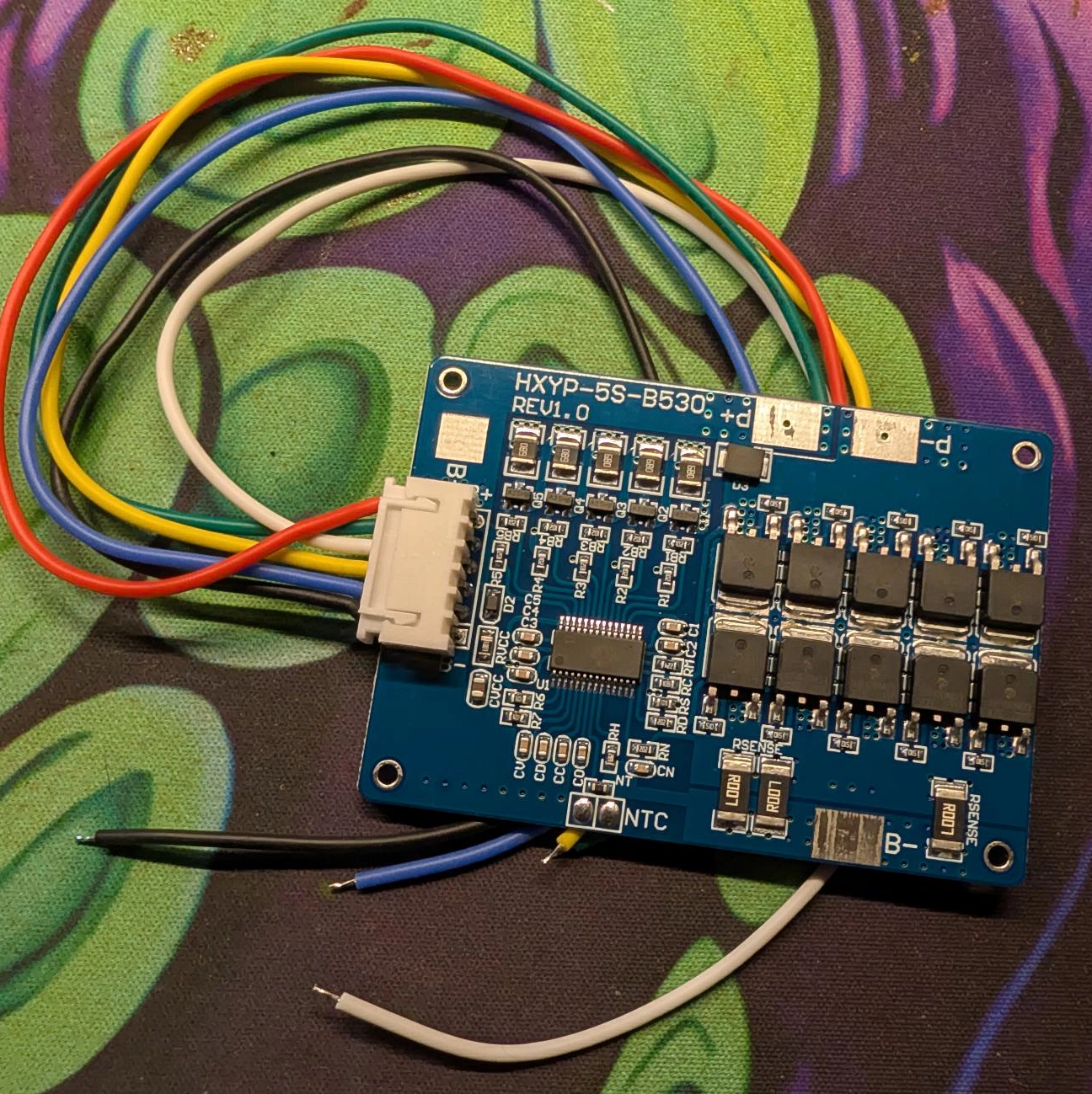
build itself is the point, roll your own — and to match a tool pack exactly, a
5S board like the HXYP-5S-B530 (30A continuous, 45A peak, with balancing)
builds a loose pack at the same 18–21V, minus the rugged case. Either way the
two rules that matter are the same: know your polarity, and fuse the positive
leg at the pack.
[ See Also ]
Using a Basic Multimeter # the "meter it" tool this guide keeps asking for
DIY 18650 Pack + Daly BMS # the roll-your-own alternative, 12V or 24V
Battery Pack Calculator # size a roll-your-own pack: voltage, Ah, Wh, current
Meshtastic Node Build # a portable load worth powering off a tool pack
ESP32 Getting Started # the three ways to power a board, and the 3.3V rules
DIY Power over Ethernet # the other cheap way to get power where you need it