
[ Wiring a 5S BMS into a DIY 20V 18650 Pack ]
[ Overview |
What "5S / 20V" means |
The board |
The balance ladder |
Wiring order |
Charging |
Fusing & protection |
What goes wrong ]
[ Overview ]
This is the roll-your-own counterpart to the tool-battery guide. Five 18650s
in series and a 5S BMS give you a 20V pack that is, electrically, a power-tool
battery — the same voltage, your choice of cells and capacity, and none of the
rugged case or charger ecosystem you get from buying one.

It is also the big brother of the 3S Daly build. The principles are identical:
the board switches only the negative leg, pack positive is a pass-through, the
load lands on P− (never B−), the balance order can kill the board, and the
NTC has to be plugged in. Rather than re-explain all of that, this guide points
back to the 3S build for the shared fundamentals and focuses on what is
different at 5S: two more cells, a six-wire balance ladder, and a 21V charger.

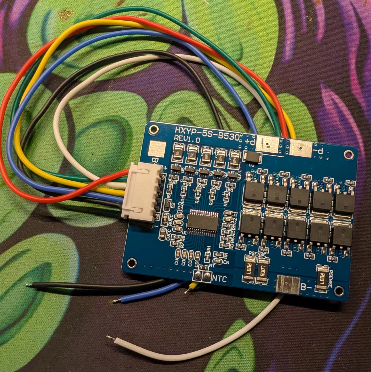
The worked example is an HXYP-5S-B530 board with five cells — the same board
from the tool-battery guide's build-your-own note.
Safety, once, plainly. A finished 5S pack sits at up to 21V and can source
tens of amps into a short without noticing — enough to weld metal to the
terminals, burn you, and start a fire. Build one connection at a time, insulate
as you go, keep the balance leads away from the main current path, and never
leave a half-built pack with bare leads on the bench. Use cells of matched
capacity and voltage; a mismatched series pack is the thing that fails.
[ What "5S / 20V" means ]
Five lithium-ion cells in series (5S):

  full        21.0 V     4.2 V / cell
  nominal     18.5 V     3.7 V / cell
  empty       15.0 V     3.0 V / cell

That is the tool-battery band. A “20V MAX” DeWalt, a Milwaukee M18, a Makita
18V LXT — all 5S inside, all living in this 15–21V window. Build a 5S pack and
you have made the same thing, which is exactly why the numbers here match the
tool-battery guide.

For real runtime you go 5S2P or 5S3P: two or three cells in parallel per
series position, ten or fifteen cells total. The BMS still sees five groups;
each one is now a parallel set, and the balance tap lands on the group. Cells in
a group must be matched and at the same voltage before you join them — the same
rule, and the same reasons, as the 4S/6S note in the 3S guide.
[ The board ]
The example board is an HXYP-5S-B530, a common 5S lithium-ion BMS:

  cell count         5S (four intermediate taps + the two ends)
  continuous         30A, 45A peak
  balancing          passive, ~56 mA bleed
  cell cutoffs       over-discharge ~2.8V, overcharge ~4.25V per cell
  quiescent draw     < 30µA (negligible self-drain)

Its pads are labelled B+, B−, P+, P− and NTC, plus the six-wire
balance connector. As on any low-side BMS, B− goes to the pack's negative and
P− is the switched negative out to the load; the positive is a pass-through, so
B+ and P+ are the same net broken out to two pads. Read your own board's
silkscreen and meter it to confirm before you wire — clones relabel things.
[ The balance ladder ]
A 5S board has six balance wires: pack negative, then one at each of the four
cell junctions, then pack positive. Measured from pack negative, each is the sum
of the cells below it, so with every cell full the ladder reads 0 up to 21V:

      ●───────────  B6   pack +               21.0 V
      │
   ┌─┴────┐
   │ cell 5 │
   └─┬────┘
      ●───────────  B5   cell4 + / cell5 −   16.8 V
      │
   ┌─┴────┐
   │ cell 4 │
   └─┬────┘
      ●───────────  B4   cell3 + / cell4 −   12.6 V
      │
   ┌─┴────┐
   │ cell 3 │
   └─┬────┘
      ●───────────  B3   cell2 + / cell3 −    8.4 V
      │
   ┌─┴────┐
   │ cell 2 │
   └─┬────┘
      ●───────────  B2   cell1 + / cell2 −    4.2 V
      │
   ┌─┴────┐
   │ cell 1 │
   └─┬────┘
      ●───────────  B1   pack −                 0 V  (reference)

Connect it bottom-up, one wire at a time, and measure the ladder before the
plug goes near the board. Each sense input expects one cell above the one below
it; plugging the connector in out of order, or with the pack half-assembled, can
put many volts across an input rated for a few, and that kills the board.
This is the single most dangerous step, and it is spelled out in full in the
3S guide's balance-taps section — the danger is identical at 5S,
just with two more rungs.
[ Wiring order ]
Same sequence as the 3S build, two cells longer. Each step assumes the previous
one checked out.

  1. Build and check the pack. Five cells (or groups) in series, and measure
     the tap ladder from pack negative: 0, ~4.2, ~8.4, ~12.6, ~16.8, ~21.
  2. Balance leads on, bottom-up. B1 (pack −) first, then each junction in
     order, then B6 (pack +) last.
  3. Plug in the NTC. Bead taped to a cell, not the board. Most 5S boards
     will not enable their output without it.
  4. Connect B−. Pack negative to the board's B− pad, heavy gauge and
     short — it carries full current and is the board's reference.
  5. Connect P− to the load (and the charger, on a common port).
  6. Connect B+ to the load (and charger). This leg does not pass through
     the BMS.

The diagram below is the 5S version of the wiring; it is the same shape as the
3S and 4S diagrams in the Daly guide, with five cells and a six-wire ladder.
[ Charging ]
A 5S pack wants a CC/CV supply that terminates at 21V (4.2V per cell). Constant
current until the pack reaches 21V, then constant voltage while the current
tapers off, then stop.

  — A charger for the matching tool platform (a 20V / 18V tool charger) is the
    easy answer if you have one — it already does 21V CC/CV.
  — A bench supply set to 21V with a sane current limit works as a manual
    CC/CV charger. Do not walk away from it.
  — Never use a nominal-voltage wall supply (never fills the pack) or a
    lead-acid charger (floats far past 4.2V per cell).

Charge current at 0.5C per parallel cell is comfortable, and the BMS balances
only near the top of the charge, so run the pack to full occasionally and let it
sit on the charger a while after the current tapers.
[ Fusing & protection ]
The 5S board's own protection is per-cell cutoff (~2.8V low, ~4.25V high),
over-current, and temperature — but its over-current trip is set to protect the
board, not your wiring. A 30A board will pass 15A through a pinched wire feeding
a 3A load until something melts.

  — Inline fuse on B+, at the pack, sized just above your real peak draw.
    The wire between the cell and the fuse is the only unprotected copper in the
    build, so keep it short. This is the same rule, and the same reasoning, as
    the 3S guide's fusing section.
  — Wire gauge. Size the main leads — B+, B−, P− — to the
    board's rating, not your load. For this 30A / 45A-peak board that is 12 AWG
    at a minimum, 10 AWG if you will pull near the full rating, in silicone
    stranded wire. All three carry the same full current, so match their gauge;
    the balance harness stays thin (it only senses voltage).
  — A low-voltage cutoff for anything unattended is optional here — the
    5S board already cuts at ~2.8V/cell — but an XH-M609-style disconnect set
    around 16–16.5V stops the pack earlier than the board's floor and is easier
    on the cells over the long run.
[ What goes wrong ]
The 5S failure modes are the 3S ones, scaled up:

  load on B−        Works perfectly, protects nothing. Trace the load's
                     negative and confirm it lands on P−, not B−.
  balance order      Six wires means two more chances to plug the ladder in
                     out of order and kill the board. Bottom-up, measured.
  wrong charger      21V CC/CV only. A 20V supply never fills it; a lead-acid
                     charger cooks it.
  NTC unplugged      No output on most boards, and no thermal protection on
                     the rest.
  mismatched cells   A weak cell group defines the whole pack and drops out
                     first. Match capacity and voltage before assembly.
  no fuse            The 30A board is not your wiring's fuse. Add one on B+.

Everything here is the low-side-BMS story you already know from the
3S build — this guide just runs it at 21V. If you want the bought version of the
same 20V pack instead of building one, that is the tool-battery guide.
[ See Also ]
Battery Pack Calculator # size the pack (voltage, Ah, Wh, current) before you build it
Wiring a Daly BMS (3S / 12V) # the fundamentals, in full — this guide leans on it
Using a Power-Tool Battery # the bought 20V pack this one rebuilds from scratch
Using a Basic Multimeter # the meter checks on every tap and terminal
Using a Bench Power Supply # CC/CV charging to 21V, done carefully
lygte-info.dk # independent 18650 discharge curves and capacity tests