
[ Using a Bench Power Supply ]
[ Overview |
CV and CC |
Set it up first |
The safety net |
Reading it |
What it's for |
Floating outputs |
What goes wrong ]
[ Overview ]
If the multimeter is the tool that tells you what a circuit is doing, the
bench power supply is the one that powers it on your terms. It is an adjustable
DC source with two things a battery and a wall wart don't give you: a voltage
you dial to anything you want, and a current limit — a ceiling on how much it
will deliver, no matter what the load asks for.

That current limit is the whole point. A charged battery or a wall adapter will
happily pour everything it has into a short or a backwards part and cook your
board before you smell it. A bench supply, set up right, notices the load
pulling too hard and simply clamps the current instead — the difference between
“huh, that's not right” and a dead project.

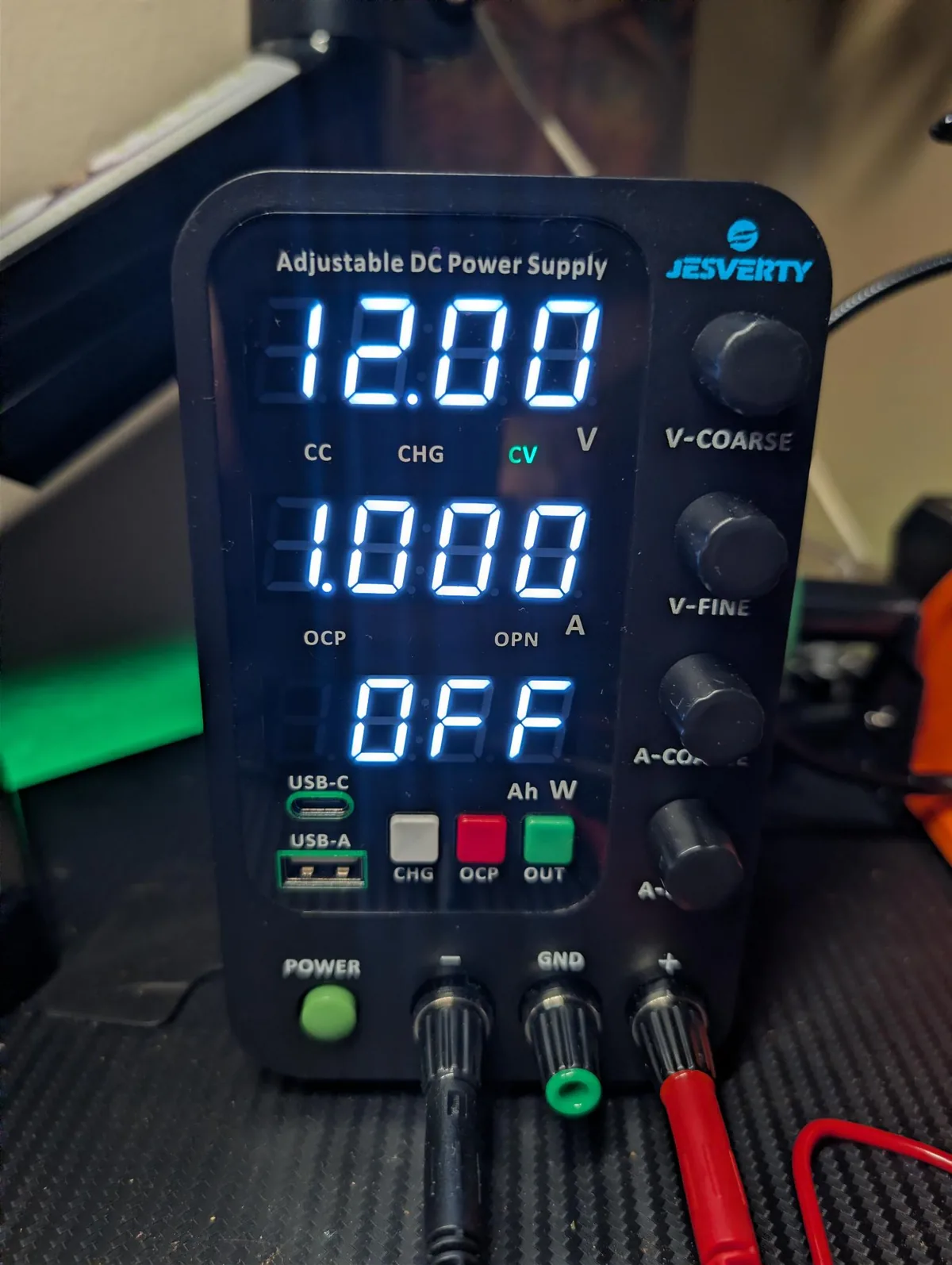
The worked example is a generic benchtop supply with a voltage knob, a current
knob, an output on/off button, and a display reading volts and amps. They all
work the same way, whether it is a $40 single-channel unit or a lab bench full
of them. Everything here is about those two knobs and the one idea behind them.
[ Two modes: CV and CC ]
A bench supply is always in one of two modes, and it flips between them on its
own. Understanding the flip is 90% of using one well.

  — Constant voltage (CV)  the normal state. You set a voltage; the supply
    holds it steady and delivers whatever current the load happens to draw. A
    board that wants 5V at 0.2A gets 5V, and the supply reports 0.2A.
  — Constant current (CC)  the safety state. The moment the load tries to
    pull more than the current limit you set, the supply stops holding the
    voltage and starts holding the current instead: it drops the voltage to
    whatever keeps the current pinned at your limit.

The supply crosses from CV to CC automatically at the limit, and a little
CV / CC indicator tells you which one it is in. In normal use you live in CV
and the CC light never comes on. When it does, the supply says the load
is drawing everything you allowed — either because it genuinely needs that much,
or because something is wrong.
[ Set it up before you connect ]
The order matters. You want both knobs set before anything is wired to the
output, so the first thing the circuit sees is correct and current-limited.

  1. Output off. Set the voltage and current with the output disabled, so
     nothing is live while you dial.
  2. Set the voltage. Turn the voltage knob until the display reads what your
     circuit wants — 3.3V, 5V, 12V, whatever. With no load, the voltage reading
     is exactly your setpoint.
  3. Set the current limit. Two ways:
       — By dialing: turn the current knob to just above your circuit's
         expected draw. A board you think pulls 150mA? Set ~250mA and leave
         margin for inrush.
       — By shorting: clip the two output leads together, which forces CC
         mode, and turn the current knob until the display reads the exact limit
         you want. Then remove the short. This sets the cap precisely.
  4. Connect the circuit, red to +, black to −, with the output still off.
  5. Enable the output and watch the current reading as it comes alive.

If the CC light comes on the instant you enable the output, kill it — the load
is pulling to your limit at once, which on a circuit that should sip current
means a short or a backwards part. You just caught it before it caught fire.
[ The current limit is a safety net ]
This is worth its own section because it is the reason to reach for a bench
supply over a battery in the first place.

Set the limit a little above what the circuit should draw, and the supply
becomes a tripwire. Everything working normally? You sit in CV, the load takes
its 150mA, life is good. A solder bridge, a backwards diode, a chip in upside
down, a probe that slips? The load lunges for more current, the supply hits the
limit, drops into CC, and holds the current right there. Your mistake gets a few
hundred milliamps at a sagging voltage instead of the tens of amps a battery
would have delivered — usually the difference between a warm chip you can still
save and a scorched board.

A few habits make the net tighter:

  — Start low. On an unknown board, set the limit low (say 100–200mA) and
    bring it up only if the circuit legitimately needs more. A low limit turns a
    short into a shrug.
  — Watch the first power-up. The current reading at the moment of
    enabling is the most informative number you'll see. It should settle at the
    draw you expected.
  — Match the limit to the weakest thing. If a board has a 500mA part on
    it, do not set the limit to 3A just because the supply can.
[ Reading the display ]
Most supplies show two live numbers, volts and amps, and sometimes a third for
watts. The trick is knowing which are set values and which are actual.

  — In CV: the voltage shown is your setpoint (actual = set), and the
    current shown is the real draw of the load. The amps number is your
    ammeter — it tells you exactly what the circuit is pulling.
  — In CC: now it flips. The current shown is your limit (actual = set),
    and the voltage shown is the real sagging voltage the load is getting.

So the CV/CC light is not decoration — it tells you which two of the four
numbers are the honest measurements. In CV, trust the amps. In CC, trust the
volts, and ask why you are in CC at all.

Many supplies also have memory presets (M1, M2…) so you can store, say,
3.3V and 5V and recall them without re-dialing. Handy once you settle on a few
working voltages.
[ What you'll actually use it for ]
Beyond “power this at 5V,” a few jobs come up constantly:

  — Bring up a new board safely. Current-limited first power-on, as
    above. The bench supply's whole reason to exist.
  — Measure a device's draw. In CV the amps reading is a live ammeter,
    no need to break the circuit like you would with a meter in series. Watch
    idle vs active current, spot a stuck peripheral, size a battery.
  — The brownout sweep. Feed a device its nominal voltage, then walk the
    voltage knob down and watch where it resets or cuts out. That is how you
    find the real low end of a “12V” radio, or where a tool-battery load
    quits — far safer than draining an actual pack to find out.
  — Careful cell work. A supply set to 4.2V with a sane current limit
    is a manual CC/CV charger: it holds the current until the cell reaches 4.2V,
    then tapers. Useful for reviving or topping a single 18650 — but there is
    no protection and no safe auto-stop beyond that taper, so never walk away
    from it, and for a real pack use a proper charger and BMS.
  — Burn-in and load testing. Hold a voltage on something for an hour and
    watch the current stay put — or drift, which tells you something is heating
    up and changing.
[ Floating outputs ]
One thing that trips people up: on most bench supplies the output is floating
— neither the + nor the − terminal is tied to mains earth. That is deliberate
and useful:

  — You can reference either terminal to your circuit's ground. The supply
    doesn't care which side you call ground.
  — You can series two supplies (+ of one to − of the other) to get a
    higher voltage than one alone, or a split rail (say ±12V), because neither
    is pinned to earth.

Bigger supplies add a separate earth-ground post next to the + and − outputs,
for tying your circuit's ground to mains earth when you want it (noise, safety
on mains-referenced work). It is a third, independent terminal — not one of the
two output rails. If your model has one, know that it is optional and separate.
[ What goes wrong ]
The usual traps.

  limit set too high    The safety net only works if it is set. A 3A limit on
                       a 200mA board means a short gets 3A — enough to do
                       damage. Set the limit to the circuit, not the supply.
  forgot the order     Wiring the circuit with the output live, or dialing
                       voltage into a connected load, means the first thing it
                       sees may be wrong. Set both knobs with the output off.
  reversed polarity    Red to +, black to −. A supply will happily push current
                       the wrong way into a board. Check before enabling.
  lead voltage drop    Long or thin leads drop voltage under load, so the
                       board sees less than the display shows. It reads the
                       voltage at its own terminals, not at your circuit —
                       measure at the load with a meter if it matters.
  inductive kickback   Motors, relays and solenoids fling a reverse voltage
                       spike when switched off. Put a flyback diode across the
                       coil so the spike doesn't come back at the supply.
  walked away from a cell A supply charging a cell has no BMS and no real
                       cutoff. Stay with it, or don't do it. Packs get a
                       proper BMS.

None of it is hard. Set the voltage and the current limit with the output off,
keep the limit close to what the circuit should draw, and the supply spends its
life quietly doing exactly what you told it — and catching you the day you make
a mistake.
[ See Also ]
Using a Basic Multimeter # the other half of the bench: measure what the supply powers
Using a Power-Tool Battery # the brownout sweep, done safely on the bench
DIY 18650 Pack + Daly BMS # why a real pack wants a charger and BMS, not a PSU
ESP32 Getting Started # current-limited 3.3V bring-up of a new board