
[ Solar Power Basics ]
[ Overview |
Reading the label |
Wiring |
Series vs parallel |
PWM vs MPPT |
Sizing |
Battery bank |
Safety |
FAQ ]
[ Overview ]
Solar is the other half of an off-grid build: the battery stores the
energy, the panel refills it. This is the groundwork: what a panel's numbers
actually mean, how to wire several of them together, and the one component
between panel and battery that decides how much you keep: the charge
controller.

None of it is specific to a big roof array. It's the same physics for a single
100 W panel keeping a Meshtastic relay alive as for a cabin bank. Read the
label, wire two panels the right way, and pick the right controller, and you
won't cook a battery or throw away a quarter of your power.
[ Reading the label ]
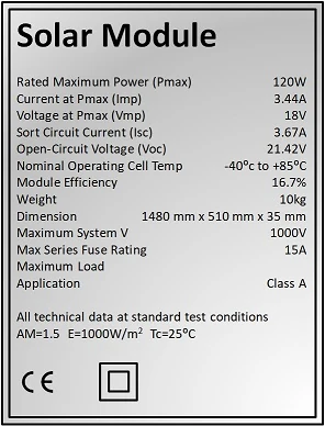
A solar panel in daylight behaves like a current source: sunlight sets how
much current it can push, and it delivers that at whatever voltage the load
allows, up to a ceiling. The label's five numbers describe that curve.

  Voc    Open-circuit voltage — nothing connected, the highest voltage
         the panel reaches. This is the number that must stay under your
         controller's max input, and it rises in the cold (see Sizing).
  Vmp    Voltage at max power — roughly 80% of Voc; where the panel
         makes the most watts. A controller's whole job is to hold the
         panel here.
  Isc    Short-circuit current — leads shorted together, the highest
         current the panel can pass. Safe to measure; it won't hurt the panel.
  Imp    Current at max power — a hair below Isc.
  Pmax   Rated watts = Vmp × Imp, e.g. a “100 W” panel.

Two things the label won't shout. First, “12 V” on a panel is a
nominal label, not its real voltage: a 12 V panel has a Vmp around 18 V,
sized to charge a 12 V battery through a controller. Second, every number is
STC: a lab at 1000 W/m² and 25 °C. Real roofs are hotter and hazier
(heat drops the voltage, haze and dust drop the current), so a panel makes
25–30% fewer watts in the real world than its rated Pmax. Size around a
100 W panel behaving like a 70–75 W one. You can confirm Voc and Isc yourself
with a multimeter: Voc across the leads on volts, Isc across them on the
10A jack, in full sun.
[ Wiring & polarity ]
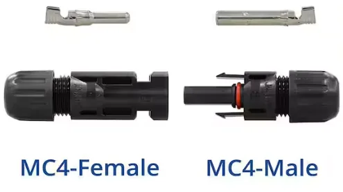
Most panels terminate in a pair of MC4 connectors: keyed, click-locking,
weatherproof, and polarised so you can't cross + and − by accident. A panel's
positive lead ends in one MC4 gender and negative in the other, which is what
makes series chaining just plug-into-plug.

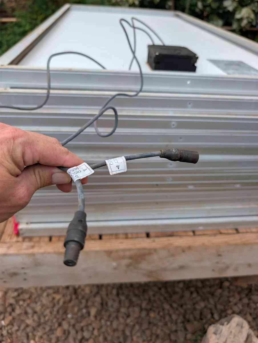
MC3 is the older predecessor you'll meet on panels from before ~2011: same
idea, but a single push-together contact with no locking latch. MC3 and MC4
do not intermate. Never force one into the other, and don't mix them in a
string. Old MC3 panels are often labelled “do not disconnect under load”,
since the unlatched contact can't break a DC arc safely; the clean modern fix is
to cut the MC3 ends off and crimp on proper MC4s with the right tool, minding
polarity.
  — Polarity matters. Not every controller protects against reversed
    panel leads; get + and − right before you connect. Red is +, black is −.
  — A lit panel is always live. There's no off switch on the sun. To work
    safely, cover the panel or wait for dark. Don't rely on “it's cloudy.”
  — Don't break a connection under load. DC arcs don't self-extinguish the
    way AC does. Disconnect at the controller first (or cover the panel), so
    no current is flowing when the MC4 pops apart.
  — Size the wire for the array current and the run length; long runs
    drop voltage, and a higher-voltage (series) array loses less to that drop.
  — Match connector brands. Two “MC4-compatible” connectors from
    different makers often mate loosely, and that high-resistance joint is a
    documented cause of rooftop fires. Same brand throughout.
  — Crimp, don't solder. Solder wicks up the strands and leaves a stiff
    spot that work-hardens and cracks. Crimp MC4s with the proper die.
  — A disconnect each side. A DC-rated disconnect between array and
    controller, and another between controller and battery, so you never have
    to break a live circuit by hand.

Cable and hardware. Outdoors, use cable rated for it: PV Wire or
USE-2, made for UV and wet exposure. Plain THHN in sunlight goes brittle in a
couple of years. On the coast, use tinned-copper conductors and stainless
hardware; untinned copper corrodes at the connector barrel where you can't see
it, and a corroded joint is a resistive joint, which is a heat source. Once a
year, IR-scan the combiner and connectors under load on a sunny afternoon to
catch a failing joint before it fails.

The battery side of the controller connects to a pack with its own protection;
if you're building that pack, see the BMS guide.
[ Series vs parallel ]
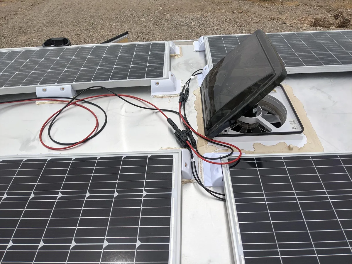
This is the choice that trips everyone up, and it's just Kirchhoff. Wire panels
end-to-end (series) and the voltages add. Wire them side-by-side, all the
pluses together and all the minuses together (parallel), and the currents
add. Same total power either way. You're just trading volts for amps.
Series: each panel's − to the next panel's +. Voltage adds, current
stays the same. Three 20 V · 5 A panels become a 60 V · 5 A array.
Parallel: all + to one rail, all − to another. Current adds, voltage
stays the same. The same three panels become a 20 V · 15 A array.
Bigger arrays combine the two (strings of panels in series, those strings in
parallel) to hit a target voltage and current. But the choice between them
isn't free: it's dictated by the controller you're feeding, which is the next
section.
[ PWM vs MPPT ]
A charge controller sits between array and battery. Its job is to stop the
panel from boiling the battery (running the proper bulk / absorb / float
charge stages) and to get as much of the panel's power into the pack as it
can. There are two kinds, and the difference is real money and real watts.

PWM (pulse-width modulation) is, in effect, a fast switch that ties the
panel directly to the battery. Because they're connected, the panel is dragged
down to the battery's voltage, so an 18 V (Vmp) panel charging a 13.6 V
battery runs at 13.6 V, and the 4-ish volts of headroom are simply lost. That's
fine only when Vmp is already close to battery voltage. PWM is cheap, simple,
and reliable for a small, voltage-matched system; its rating is a current limit,
so your array's Isc must sit under it, and the array's nominal voltage must
match the battery's.

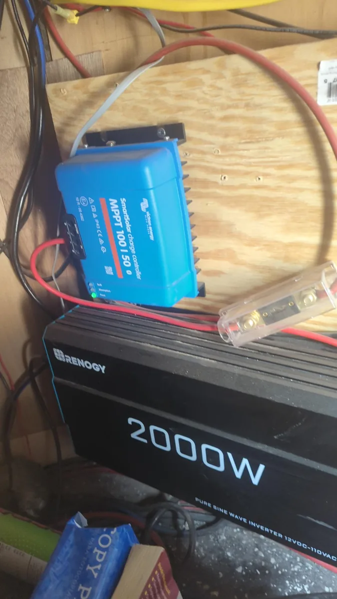
MPPT (maximum power point tracking) is a DC-DC converter. It holds the panel
at its Vmp and converts the surplus voltage into extra current on the way to
the battery, the same trick a buck converter does. Volts you'd have thrown
away with PWM come back as charge current, typically 20–30% more harvest, and
more than that in the cold or when the array voltage sits well above the
battery. It also lets you run a high-voltage series string into a low-voltage
battery, so you get thin wire and long runs for free. It costs more and has a
max input voltage you must respect (see Sizing).
The short version:

  — small, cheap, panel Vmp already near battery voltage → PWM.
  — want the most harvest, a series string, long runs, or cold winters
    → MPPT.

On anything bigger than a trickle-charger the MPPT pays for itself in panel you
didn't have to buy.
[ Sizing it right ]
Three things have to agree: the array, the controller, and the battery.

  — Battery voltage is the anchor: 12, 24, 48 V. You set it in the
    controller (or it auto-detects).
  — Array voltage vs the controller. On PWM, the array's nominal
    voltage must equal the battery's, so you add panels in parallel. On
    MPPT, you add panels in series to raise voltage, up to but safely
    under the controller's max input.
  — Controller current. Size it for the array. On MPPT the output
    current can exceed the array's Imp, because watts in at high volts come
    out at higher amps: roughly array watts ÷ battery volts.

The cold-Voc trap. A panel's Voc climbs as it gets colder, about
+0.3%/°C below 25 °C. A series string reading 90 V on a warm afternoon can push
past 100 V on a clear, freezing morning before any load is drawn, and if that's
over the MPPT's max input it kills the controller. Worse, that failure often
shorts the input straight to the battery bus. Size the string on its
cold-adjusted Voc at the coldest temperature you expect, not the number
you measured in summer.
A worked example. Three 100 W panels (each Voc 22 V, Vmp 18 V,
Isc 6 A) into a Victron MPPT 100/50 on a 12 V bank. Wire them in
series, then walk the three checks:

  Voltage.  3 × 22 V is 66 V Voc on a warm day. Cold-adjust for a
            −10 °C morning: +0.3%/°C over 35 °C is +10.5%, so about 73 V.
            That clears the controller's 100 V ceiling with room to spare.
  Current.  300 W into a 12 V bank is 300 ÷ 12, about 25 A out of
            the controller (use nominal battery volts; output peaks when the
            battery is low). Well under its 50 A rating.
  Fusing.   One series string, so no string fuses. Size the battery fuse
            for the ~25 A output plus headroom, say a 30 A Class T, inches
            from the + terminal.

Wire the same panels in parallel and you'd get 22 V at 18 A instead.
The 100/50 handles that fine, but now the roof-to-controller run carries 18 A,
not 6, so it needs fatter wire, and past two strings each one wants a fuse.
Series is the usual answer for MPPT, and this is why.
Run your own numbers through it. Defaults are the example above; change the
panel, count, wiring, or controller and the checks update as you type.
[ The battery bank ]
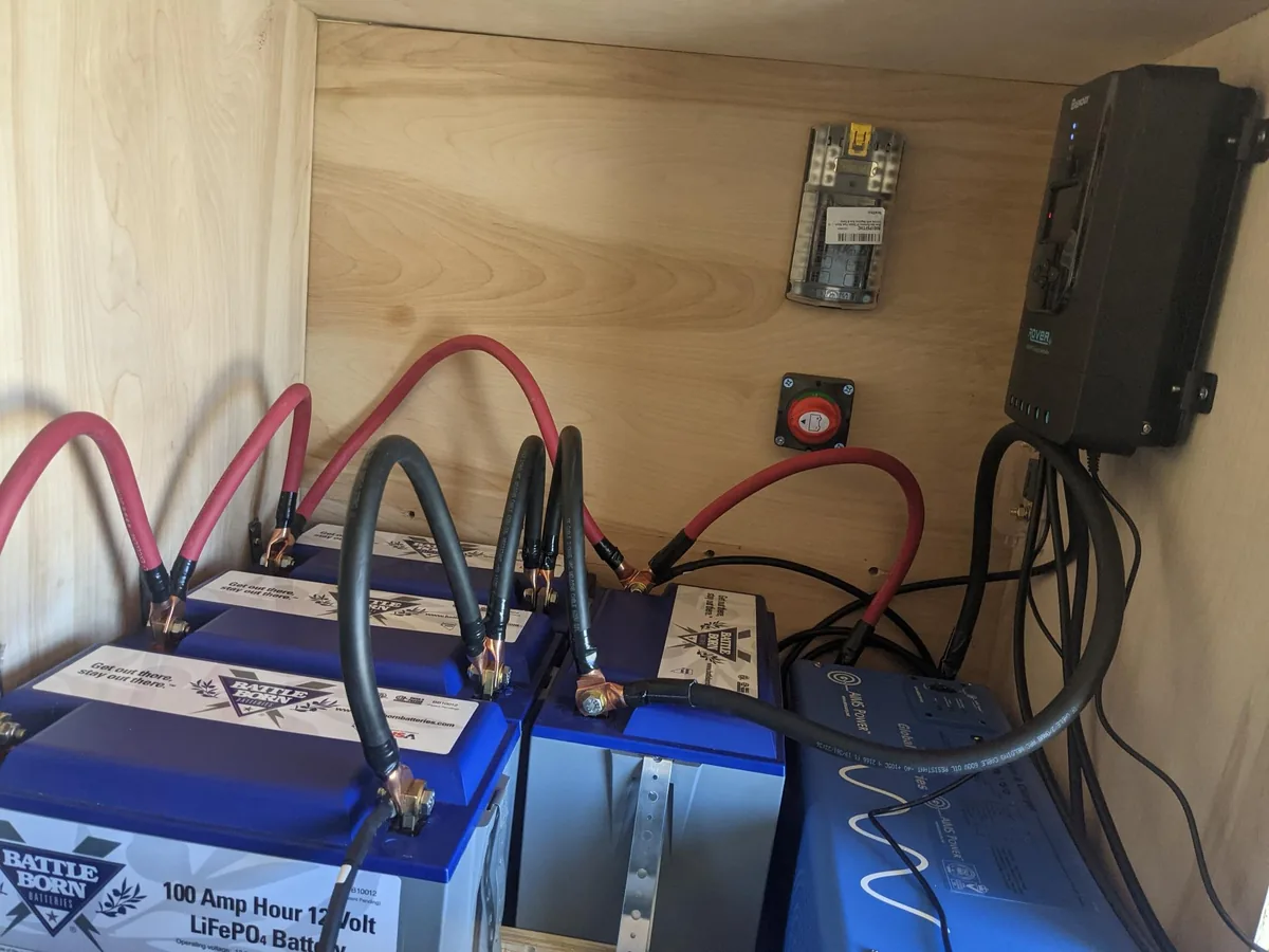
The controller charges a bank, and for anything portable that bank is
almost always LiFePO4 now: lithium iron phosphate, the safe, long-lived
lithium chemistry. A 12 V drop-in is four cells in series (3.2 V each, 12.8 V
nominal) with a BMS built in, shaped to replace a lead-acid battery. I've run
Battle Born 100 Ah drop-ins for years and haven't looked back at lead.

Why lithium beats lead-acid here:

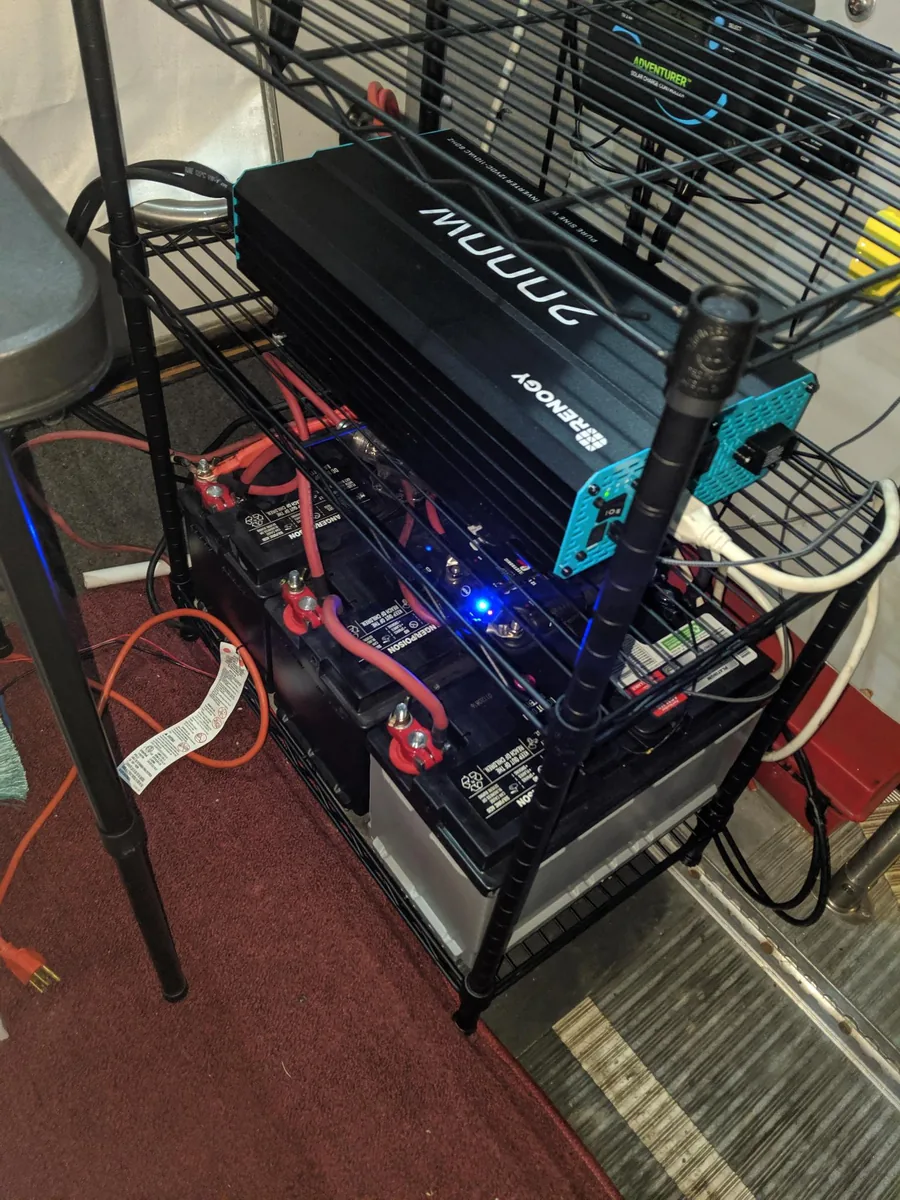
  — Usable capacity. You can pull LiFePO4 down to ~90% without hurting
    it; lead wants to stay above 50%. One 100 Ah lithium is worth nearly two
    100 Ah lead batteries in real, usable amp-hours.
  — Cycle life. Thousands of cycles, against lead's few hundred.
  — Weight and voltage. Roughly half the weight, and a flat curve that
    holds around 13 V until it's nearly empty instead of sagging all the way
    down.
  — Charging. Takes charge fast, and doesn't gas or vent.

Set the controller to a lithium profile. LiFePO4 wants a bulk/absorb
around 14.4–14.6 V and little or no float (~13.6 V, or off). Pick the
controller's Li / LiFePO4 preset, or set it by hand. Don't leave it on the
lead-acid or AGM profile: the voltages are wrong, and lithium hates being held
at a high float.

The cold-charging catch. Charging LiFePO4 when it's freezing plates
lithium and shortens its life, so every drop-in's BMS locks out charging below a
set point near freezing (Battle Born's is 24 °F / −4 °C). Some add
internal heaters so they can take a charge in the cold anyway. Discharging cold
is fine; charging cold is not.

Wiring a bank. Put drop-ins in parallel to add amp-hours at the
same voltage, and in series only if the battery is rated for it (many 12 V
drop-ins allow up to four in series for 48 V, some none). Match their age and
charge state before you connect them. The bank still needs its own fuse: a
Class T at the positive terminal, per Safety, because the internal BMS
protects the cells, not your wiring.
Rolling your own from cells instead of buying a drop-in is a different project:
the DIY 18650 + BMS guide covers that side.
[ Safety ]
  — Treat a lit panel as always on. You can't switch off the sun; cover
    the panel to work on it.
  — Break connections at no load. DC arcs sustain themselves, so open the
    circuit at the controller, or cover the panel, before unplugging.
  — Respect the controller's max input voltage, cold-adjusted. Over it is
    a dead controller.
  — Fuse both sides (below): the battery lead is the one that matters most,
    and parallel strings of three or more need one each.
  — The battery has its own rules. Charge voltages and protection belong to
    the pack; the BMS guide covers that side.
Why fusing matters. A panel is current-limited: it physically can't
push more than its Isc, so a shorted panel can't run away. A battery can. A
charged pack dumps thousands of amps into a short without blinking, enough to
vaporise a wrench, so this is where the real danger lives.

The battery fuse is the urgent one. Every battery needs a DC-rated fuse
or breaker as close to the positive terminal as you can get it, inches, not
feet, because that stretch of cable is unprotected by definition. For lithium, a
Class T fuse is the usual pick for its high interrupt rating. This is
separate from, and more urgent than, string fusing.

String fuses handle back-feed. Picture four strings on shared rails: three
healthy ones each pushing 10 A toward the combiner, and a fourth with a short.
That faulted string becomes the lowest-resistance path, and the other three dump
30 A backward into wire rated for 10. The controller never sees it, because the
fault is upstream of it. That's the fire. So with one or two parallel strings
you don't need fuses (the worst back-feed a string sees is 1× Isc, under its
own limit); at three or more, each gets a fuse in its positive lead at the
combiner. Size by NEC 690.8: 1.56× Isc, rounded up to a standard size,
then capped at the module nameplate's max series fuse rating (usually
15–20 A), the number that protects the module itself. Use PV-specific fuses
(gPV / midget-PV class), DC-rated for the full array Voc.
Permanent and grid-tied installs pull in code that off-grid and
RV builds mostly skip. Bond every module frame and rack rail to a proper
equipment ground with listed lugs or WEEB washers; an ungrounded frame turns
into a shock hazard the moment insulation degrades. And once the DC side runs at
80 V or more on or into a building, the NEC wants two things: arc-fault
detection (690.11) and rapid shutdown (690.12), so a live 400 V roof isn't
left for firefighters to work around. Many modern MPPTs and inverters include
the arc-fault side; check that yours actually does before you count on it.
Read the label, wire for your controller, respect the cold, and fuse both
sides. The rest is just sunshine.
[ FAQ ]
PWM or MPPT: which should I get?
MPPT for almost anything: it harvests ~20–30% more and lets you run
series strings on thin wire. PWM only when the system is small, cheap, and
the panel's Vmp already sits near battery voltage.

Series or parallel for my panels?
Series adds volts (thin wire, MPPT, long runs; but shade-sensitive).
Parallel adds amps (shade-tolerant; needs a fuse per string and fatter
wire). PWM wants parallel at battery voltage; MPPT wants series.

Do I need fuses on my solar panels?
Fuse the battery lead for sure: the pack, not the panel, is what dumps
hundreds of amps into a short. One panel or one string is self-limiting, but
wire three or more strings in parallel and each needs its own fuse, since
they can back-feed a fault. Use DC-rated fuses. See Safety.

What's Voc vs Vmp?
Voc is the no-load ceiling voltage (keep it under the controller's max).
Vmp is the voltage at peak power, ~80% of Voc, where a controller holds
the panel.

Is a “12V” panel really 12 V?
No, it's a nominal label for charging a 12 V battery. Its Vmp is around
18 V and its Voc higher still.

Why did my MPPT die in winter?
Almost always the cold-Voc trap: Voc rises as temperature drops, so a
string that was fine in summer can exceed the controller's max input on a cold
morning. Size on cold-adjusted Voc.
[ See Also ]
Living Off-Grid # the bigger picture this solar feeds: power, water, hot showers
Meshtastic Node Build # where a small solar + charge controller keeps a relay alive
DIY 18650 Pack + Daly BMS # the battery the controller charges
Power-Tool Battery as a Source # buck conversion, the trick MPPT uses
Using a Multimeter # measure Voc and Isc on a real panel
Using a Bench Power Supply # CV/CC, the shape of a charge curve